Service Manual HS60.pdf - 第289页
HS -60 Se rvic e Ma nual 7 DLM2 Co l lect&Plac e Head 03/ 2003 US Issu e 7.1 0 Rep laci ng th e int erme diate d istri but ion bo ard (003 3064 8-0 5) 287 7.10 Replacing the i ntermediate dist r ibution board (003306…

7 DLM2 Collect&Place Head HS-60 Service Manual
7.9 Replacing the valve positioning drive for the placement (00368075-01) and reject circuits (00367768-01) 03/2003 US Issue
286
Æ Attach the collect&place head to the head mount (see Section 7.5.4, page 267).
7.9.6 Settings
Æ Use the SITEST program to test that the valve positioning drive is functioning correctly.
Æ Use the SITEST program to calibrate the collect&place head.
HS-60 Service Manual 7 DLM2 Collect&Place Head
03/2003 US Issue 7.10 Replacing the intermediate distribution board (00330648-05)
287
7.10 Replacing the intermediate distribution board
(00330648-05)
7.10.1 Tools and equipment
– Set of DIN 911 Allen keys
– Open-ended or socket spanner, size 5.5
7.10.2 Parts
SP6_12 intermediate distribution board, digital, item no. 00330648-05 7
7 DLM2 Collect&Place Head HS-60 Service Manual
7.10 Replacing the intermediate distribution board (00330648-05) 03/2003 US Issue
288
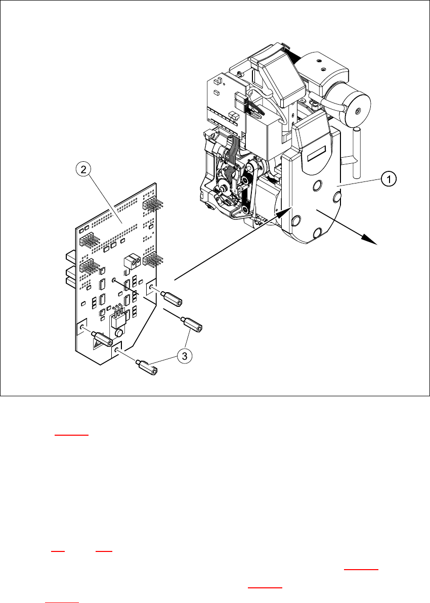
7.10.3 Dismantling the intermediate distribution board
Fig. 7.10 - 1 Dismantling the intermediate distribution board
Key to Fig. 7.10 - 1
(1) Cover
(2) Intermediate distribution board
(3) 4 x M3x10 spacer bolt
7
Æ Switch the placement system off and secure it to prevent switching on again as described in
Section 7.4
, page 261.
Æ Remove the four mounting bolts and remove the cover (see item 1 in Fig. 7.10 - 1).
Æ Remove the four M3x10 spacer bolts (item 3 in Fig. 7.10 - 1) and tilt the PCB slightly (item 2
in Fig. 7.10 - 1
).