Service Manual HS60.pdf - 第79页
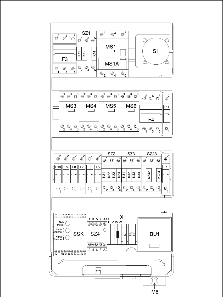
HS -60 Se rvic e Manu al 3 P owe r Su pply 03/ 200 3 U S I ssue 3. 7 Mea su rin g vo lta ge s on th e po wer su pp ly uni t 77 3 Fig. 3.7 - 1 Mea surin g volta ges on the f ront p anel of t h e powe r supp ly un it

3 Power Supply HS-60 Service Manual
3.7 Measuring voltages on the power supply unit 03/2003 US Issue
76
3.7.3 Preparing the power supply unit for measurement
The power supply unit and main switch are located in the machine frame. In front of the unit there
is a set of safety doors which can be opened with the double-bit key. 3
The unit is fixed to the machine frame using an M8 hexagon socket-head screw. 3
To measure the power supply, proceed as follows: 3
Æ Switch the placement system off at the main switch.
Æ Loosen the M8 lock screw on the underside.
Æ Pull the unit out as far as the stop.
WARNING Make sure that the main power cable and supply lines do not be-
come caught up in the placement system, otherwise the insulation will be damaged. 3
Æ Switch the placement system on at the main switch and start it up.
3.7.4 Measuring voltages on the front panel of the power supply unit
PLEASE NOTE: The placement system must be started in order to take these measurements.
This means that the protective covers and component flaps must be closed and the component
tables docked. The emergency stop button must be released and the Start button pressed. If this
is not the case, the operating voltages will not be switched through to the servo amplifiers, lifting
tables, etc. 3
The inputs to the modules all have odd numbers and the outputs have even numbers. 3
In the case of fuses (F1, etc), the input is always on the underside of the module, whereas with
contactors (SZ1, etc) and motor circuit-breakers (MS1 ...), it is always at the top. 3
HS-60 Service Manual 3 Power Supply
03/2003 US Issue 3.7 Measuring voltages on the power supply unit
77
3
Fig. 3.7 - 1 Measuring voltages on the front panel of the power supply unit

3 Power Supply HS-60 Service Manual
3.7 Measuring voltages on the power supply unit 03/2003 US Issue
78
Module Designation Terminals Voltages
X1
Terminal panel
Power supply
U, V, W
3 x 204 VAC / 3 x 230 VAC / 3 x 380 VAC
3 x 400 VAC / 3 x 415 VAC
BU1 Service socket 115 / 130 / 220 / 230 / 240 VAC
S1
Main switch
1, 3, 5 and
2, 4, 6
3 x 204 VAC / 3 x 230 VAC / 3 x 380 VAC
3 x 400 VAC / 3 x 415 VAC
MS1
Motor circuit-breaker
1, 3, 5 and
2, 4, 6
3 x 204 VAC / 3 x 230 VAC / 3 x 380 VAC
3 x 400 VAC / 3 x 415 VAC
SZ1
Main contactor
1, 3, 5 and
2, 4, 6
3 x 204 VAC / 3 x 230 VAC / 3 x 380 VAC
3 x 400 VAC / 3 x 415 VAC
SZ2
Contactor
1, 3, 5
2, 4, 6
3 x 140 VAC
3 x 140 VAC
SZ3
Contactor
1, 3, 5
2, 4, 6
3 x 140 VAC
3 x 140 VAC
SZ23
Contactor
1, 3, 5
2, 4, 6
3 x 140 VAC
3 x 140 VAC
SZ4 Contactor A1 (+) - A2 (-) 24 VDC
1, 2 24 VDC against ground
3, 4 24 VDC against ground
5, 6 24 VDC against ground
SSK
Combined contactor/
protective device L+, X3, X5 24 VDC against ground
F1 Fuse 1, 2 115 VAC / 130 VAC / 220 VAC
230 VAC / 240 VAC
against N on terminal panel X1
F3 Fuse 1, 3, 5 3 x 230 VAC
2, 4, 6
F4 Fuse 1, 3, 5 3 x 140 VAC
2, 4, 6
F5 Fuse 1, 2 100 VDC against negative pole of
rectifier V3 (see Fig. 3.7 - 2
on page 80)
F6 Fuse 1, 2 30 VDC against negative pole of rectifier
V4 (see Fig. 3.7 - 2
on page 80)
F7 Fuse 1, 2 40 VDC against negative pole of rectifier
V5 (see Fig. 3.7 - 2
on page 80)
F8 Fuse 1, 2 40 VDC against negative pole of rectifier
V5 (see Fig. 3.7 - 2
on page 80)
F9 Fuse 1, 2
10 VDC against negative pole of rectifier
V6
(see Fig. 3.7 - 2
on page 80)
F10 Fuse 1, 2 52 VDC against negative pole of rectifier
V7 (see Fig. 3.7 - 2
on page 80)
F11 Fuse 1, 2 30 VDC against negative pole of rectifier
V8 (see Fig. 3.7 - 2
on page 80)