Service Manual HS60.pdf - 第340页
8 Mo v ab le Com pon en t C h ange o ve r Ta bl e Serv i ce M an ua l H S- 60 8. 5 R es ol ving pr obl ems 03/ 2 003 U S I ssue 338 Æ P lace th e new c ommun ications uni t on the retaining brackets a nd tighten the scre…
Service Manual HS-60 8 Movable Component Changeover Table
03/2003 US Issue 8.5 Resolving problems
337
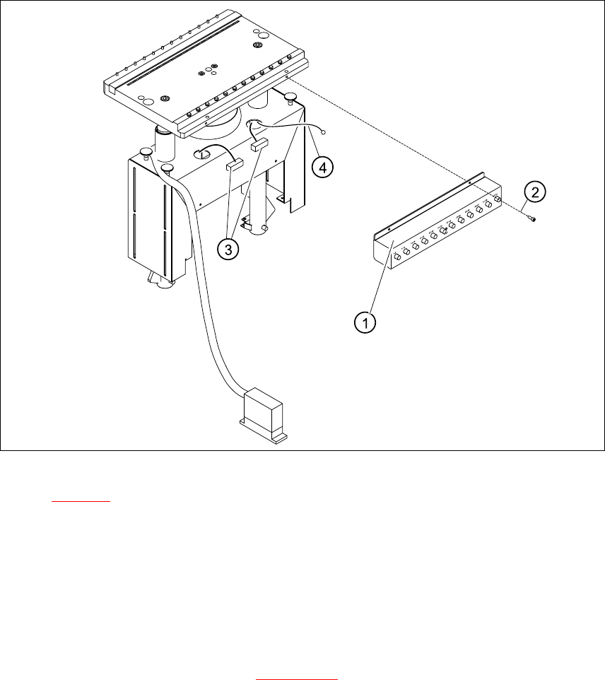
8.5.5 Exchanging the Communications Unit
Fig. 8.5.4 Exchanging communications unit; view in direction "component table termination panel"
Key for Fig. 8.5.4:
1. Communications unit
2. Fasteners for the communications unit: 4 M4 x 6 socket hex head cap screws
3. Cable "component table"
4. Ground cable with cable shoe
8
Æ Perform the "Preparatory Steps" (see Section 8.5.1).
It is not necessary to dismantle the feeder modules.
Æ Unplug the two plug-and-socket connections for the "component table“ cable, at the back of
the communication unit housing (3) and remove the ground cable (4).
Æ Hold the communication unit and undo the fastening screws (2).
Æ Remove the communication unit (1).

8 Movable Component Changeover Table Service Manual HS-60
8.5 Resolving problems 03/2003 US Issue
338
Æ Place the new communications unit on the retaining brackets and tighten the screws to fasten
it.
Æ Reconnect the „component table“ cable at the back of the communications unit housing.
Æ If you have no further parts to be exchanged, perform the appropriate "Final Steps",
including using SITEST to check the table function (see Section 8.5.7
).
Service Manual HS-60 8 Movable Component Changeover Table
03/2003 US Issue 8.5 Resolving problems
339
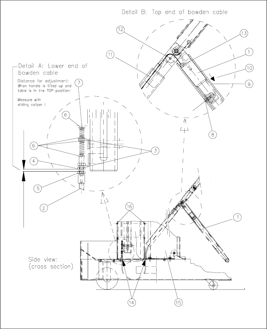
8.5.6 Exchanging the Bowden cable
8
Fig. 8.5.5 Removing/installing the Bowden cable