Service Manual HS60.pdf - 第39页
Se rv ice M a nu al HS-6 0 2 Ope rati on al saf et y 03/ 200 3 U S Iss ue 2.3 Laser clas sifica tio n 37 Plea se foll o w the instr u ctions given below to minimize the risk when placing capacitors based on powdered me t…

2 Operational safety Service Manual HS-60
2.3 Laser classification 03/2003 US Issue
36
Æ Swivel the component trolley handle up. The latching disk will also swivel up.
PLEASE NOTE:
If you cannot swivel the latching disk up to its end position, the cross-beam must be raised. 2
Æ Fix the lifting device to the crossbeam.
Æ Carefully open the crossbeam clamp.
Æ Raise the crossbeam until the end of the tube projects approx. 1mm out of the clamp.
Æ Tighten the crossbeam clamp.
Æ Then turn the adjusting screw to the desired dimension and lock in place with the locknut.
Æ Then carefully open the crossbeam clamp.
Æ Lower the crossbeam until the adjusting screw comes into contact with the latching disk.
Æ Tighten the crossbeam clamp.
Æ Then check the distance between the crossbeam and floor.
Æ Refit the internal paneling.
Æ Raise the table bed and remove the spacer block.
2.3.7 Safety instructions for processing capacitors based on powdered metal
There is a risk associated with processing capacitors based on powdered metal (e.g. tantalum).
The risk is that
– an exothermic reaction, i.e. a sudden buildup of heat, may occur, if these components are dam-
aged. If the ambient conditions are unfavorable, and depending on the capacitance, this
buildup of heat can cause damage.
– This effect can occur when these components are cut.
Please contact your suppliers to clarify whether the components that you handle are affected.
In extremely rare cases, this risk can occur in the tape cutter of SIPLACE machines, with the
remote possibility of causing a smoldering fire in the waste tape.
The ambient conditions are unfavorable if:
(1) The components remain on the tape while the set tape cycle is checked (since the operator
can cycle the feeder onward without removing components during this check).
(2) The components remain on the tape, e.g. due to a tear in the cover foil.
(3) The components remain on the tape, and the components or tape do not conform to the
specification, thus increasing the pickup error rate.
Service Manual HS-60 2 Operational safety
03/2003 US Issue 2.3 Laser classification
37
Please follow the instructions given below to minimize the risk when placing capacitors based on
powdered metal.
(1) If the component tape is cycled onward manually, the operator must remove any components
remaining in the tape pocket.
(2) If the cover foil tears, the operator must remove any components remaining on the tape.
(3) The waste tape container must be emptied regularly (recommended interval: every hour).
The feeders are labeled as shown below:
CAUTION 2
CAUTION To avoid the risk, it is essential to use only feeders that have been approved for plac-
ing such components, namely:
for model C/D item no.:00141118-01
for model E item no.:00141117-01
WARNING FIRE HAZARD 2
Æ Check and empty the waste tape container every hour.
Æ Only empty the waste tape container into suitable collection containers because of the risk of
fire. These containers must not be set up inside buildings.
2
Approved for
capacitors based on
metal-powder
Freigegeben für
Kondensatoren auf
Metallpulver-Basis
2 Operational safety Service Manual HS-60
2.3 Laser classification 03/2003 US Issue
38
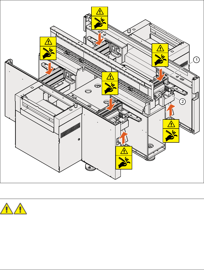
2.3.8 Safety instructions for the tape cutter
Fig. 2.3 - 3 Safety instructions for the tape cutter
WARNING RISK OF CUTTING! 2
Æ Never reach down into the used tape channel (Pos. (1)) from above with bare hands, even if
the machine is switched off.
Æ Similarly, even when the machine is switched off, do not reach up from below with bare hands
into the ejection opening of the tape cutter (Pos. 2), e.g. to remove waste used tape.
Æ To remove waste used tape, it is essential to switch the machine off first and put on very sub-
stantial protective gloves, as the tape cutter bars are extremely sharp.