Service Manual HS60.pdf - 第168页
6 Modu lar PCB conv eyor syste m Ser vic e Manu al HS- 60 6. 8 E xch an gi ng t he D C ge are d mot or of th e r el eva nt PC B c onv ey or dri ve (0 03 0092 69 -0 1) 0 3/2 00 3 U S I ss ue 166 6.8 Exchangi ng the DC gea…

Service Manual HS-60 6 Modular PCB conveyor system
03/2003 US Issue 6.7 Replacing the complete drive unit (00359284-02)
165
NOTE:
The way in which the conveyor toothed belt is run around the belt guide depends upon the trans-
port area concerned. Please observe this belt guidance during assembly.
NOTE:
If you have discovered a break in the motor cable during a continuity check, the motor cable must
be woven out as far as the conversion board of the conveyor side (see circuit diagrams of the
same name) and unplugged at the corresponding point. This may be somewhat complicated de-
pending on the routing of cables inside the machine base.
You may wish to contact Siemens Dematic AG SMD Service regarding this work.
6.7.3 Installation
Æ Install the new drive unit in the reverse order.
Æ Please check: the entire width of the conveyor toothed belt must engage at all synchronizing
disks and be run around the belt guide.
Æ Where applicable, install the guide rails on the conveyor component. Do not tighten this com-
pletely as it still needs to be adjusted.
Æ If guide rails have been loosened or remounted, you will need to readjust the alignment of the
guide rails (see Section 6.15
).
Æ Perform the „Final steps including function check“ (see Section 6.18).
NOTE:
After the new drive unit has been installed, you must make certain that the direction of rotation
and the conveyor speed (motor voltage) are correct.
After reconnecting the geared motor, you will only need to check the direction of rotation.
6 Modular PCB conveyor system Service Manual HS-60
6.8 Exchanging the DC geared motor of the relevant PCB conveyor drive (003009269-01) 03/2003 US Issue
166
6.8 Exchanging the DC geared motor of the relevant
PCB conveyor drive (003009269-01)
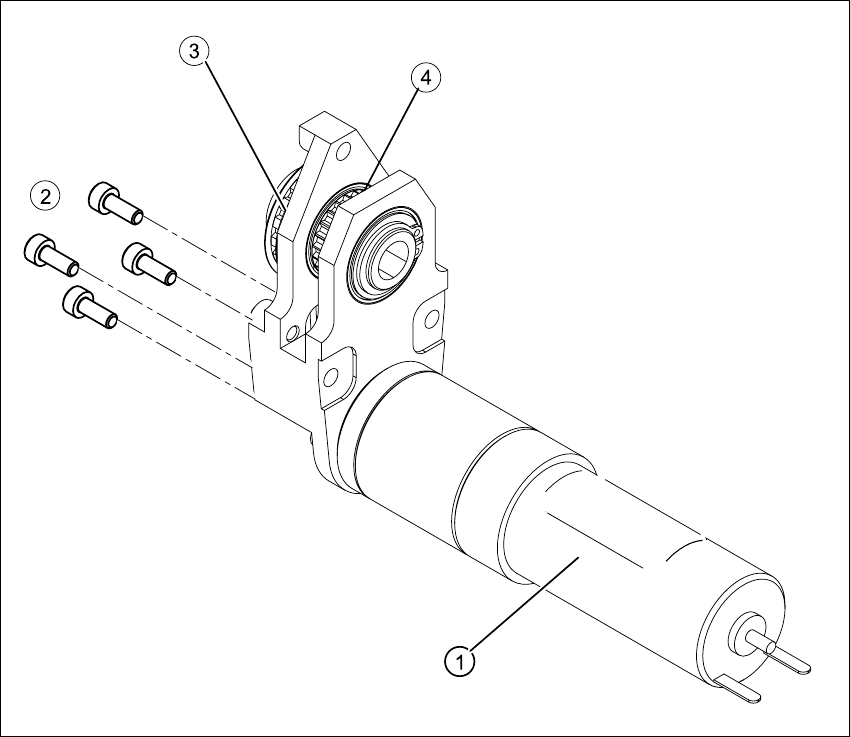
Fig. 6.8.4 Exchanging the DC geared motor of the relevant PCB conveyor drive
Key
(1) DC geared motor (3) Synchronizing disk (conveyor toothed
belt)
(2) Fastening screws (4) Synchronizing disk (toothed belt for PCB
conveyor drive)
Service Manual HS-60 6 Modular PCB conveyor system
03/2003 US Issue 6.8 Exchanging the DC geared motor of the relevant PCB conveyor drive (003009269-01)
167
DANGER
Please observe the safety instructions in Chapter 2.
CAUTION
The toothed belts must not be stretched or kinked!
6.8.1 Removal
The DC geared motors, including the motor mounts of all 5 conveyor areas, are of like construc-
tion. Please bear in mind the following differences during assembly and disassembly.
– The motor mount in installed at an angle (tilted), according to the requirements of the installa-
tion site.
– Depending upon the installation position, the motor mount will either be fixed with a clamping
ring or a circlip.
Conduct the procedures for replacement of all DC geared motors as described below:
Æ Remove the complete drive unit, as described in Section 6.7.
Æ Working from the fixed exterior side of the conveyor, undo the screws fastening the DC geared
motor (4 hexagonal socket-head screws, see Fig. 6.8.4
).
Æ Tilt the DC geared motor with its synchronized disk a little, so that the small toothed belt of the
drive comes free of the synchronizing disk and then pull the motor out.
Please note:
– The toothed belt on the motor pinion must not be stretched or kinked during this pro-
cess.
– The synchronizing disk on the motor shaft must be moved out in such a manner that is does
not get caught in the toothed belt.
NOTE:
If you have discovered a break in the motor cable during to a continuity check, the motor cable
must be woven out as far as the conversion board of the conveyor side (see circuit diagrams
of the same name) and unplugged at the corresponding point. This may be somewhat compli-
cated depending on the routing of cables inside the machine base.You may wish to contact Sie-
mens Dematic AG SMD Service regarding this work.