Service Manual HS60.pdf - 第271页
HS -60 Se rvic e Ma nual 7 DLM2 Co l lect&Plac e Head 03/2 003 US Issue 7.6 Dis mantli ng / fit tin g the fr on t part of the co lle ct&p lace he ad 269 7.6 Dismantlin g / fitting the front p art of the coll ect&…

7 DLM2 Collect&Place Head HS-60 Service Manual
7.5 Replacing the collect&place head / DLM2 (00367770-01) 03/2003 US Issue
268
Æ Make sure that the plugs are firmly locked in place.
Æ Check that the plugs of the 40-pin ribbon cables between the intermediate distribution board
and head board are correctly assigned:
Æ Make sure that the cables are not damaged and that there is no strain on the connecting ca-
bles.
Æ Connect the compressed air hoses.
7.5.5 Settings
Æ Close the protective cover.
Æ Check that you have removed all tools and equipment from inside the placement system.
Æ Start the placement system.
Æ Use the SITEST program to calibrate the collect&place head.
Cable Head board Intermediate distribution board
00333491-W1 X14 X1
00333491-W2 X13 X2
Tab. 7.5 - 2 Plug-in connections for the flat ribbon cables on the head board
HS-60 Service Manual 7 DLM2 Collect&Place Head
03/2003 US Issue 7.6 Dismantling / fitting the front part of the collect&place head
269
7.6 Dismantling / fitting the front part of the
collect&place head
7.6.1 Tools and equipment
– Set of DIN 911 Allen keys
– SITEST program
– Adjustment instructions
CAUTION Be careful with the glass scales in the sleeves. They are very fragile. 7
7.6.2 Dismantling the front part of the collect&place head
Æ Switch the placement system off and secure it to prevent switching on again as described in
Section 7.4
, page 261.
Æ Remove the connecting cable plugs from sockets X9, X13, X14 on the head board
(see Fig. 7.5 - 1
).
Æ Remove the pneumatic hose.
Æ Undo the four M3x16 hexagon socket head screws (item A in Figs. 7.6 - 1 and 7.6 - 2).
CAUTION When you undo the last screw, hold the collect&place head so that it
does not accidentally drop off the back part. 7
CAUTION When you remove the front part of the collect&place head, make sure
that the star is pivoted roughly 15° away from the vertical sleeve position. Otherwise the valve
plunger will remain attached to the valve actuator. 7
Æ Lift the front part of the collect&place head away from the parallel pins on the back part and
place on a soft, clean surface.
7 DLM2 Collect&Place Head HS-60 Service Manual
7.6 Dismantling / fitting the front part of the collect&place head 03/2003 US Issue
270
. 7
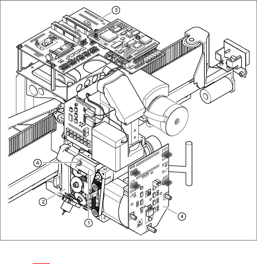
Fig. 7.6 - 1 Dismantling / fitting the front part of the collect&place head - part 1
Key to Fig. 7.6 - 1
(1) Front part of the collect&place head
(2) Back part of the collect&place head
(3) Head board
(4) Intermediate distribution board
(A) Loosen the M4x16 hexagon socket-head screw 7