Service Manual HS60.pdf - 第227页
Se rv ic e Ma nu al HS- 6 0 6 Mo du la r P C B c onve y or s y st em 03/ 2003 US Is sue 6. 14 Lig ht bar rier s and st oppe r fo r scan ning t he P CB pos i ti ons alon g the tran sport route s 225 F ig. 6. 14.3 2 D iagr…
6 Modular PCB conveyor system Service Manual HS-60
6.14 Light barriers and stopper for scanning the PCB positions along the transport routes 03/2003 US Issue
224
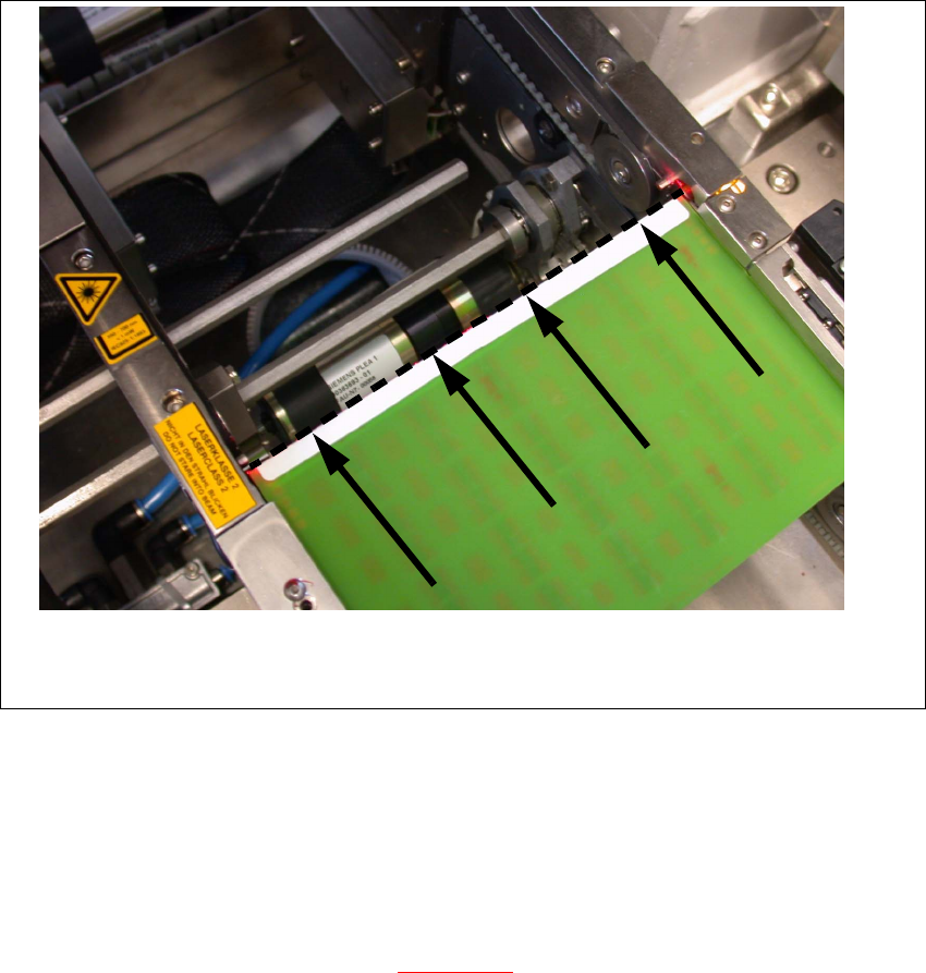
Fig. 6.14.31 Setting the laser beam
6.14.4 Setting the light barriers in the placement area
Function:
– Switch on the laser light barrier
– Start the PCB braking procedure, see Fig. 6.14.32
.
The light barrier in the placement area can be moved within a range of 50 mm. This function was
designed for PCBs with recesses on the side, to ensure that they are stopped by the laser light
barrier. In its standard version, the light barrier is installed in the direction of conveyor input, giving
the greatest distance between the light barrier and laser. The software automatically sets the slow
travel of the PCB so that it takes approx.
100 ms until it reaches the laser light barrier.
Service Manual HS-60 6 Modular PCB conveyor system
03/2003 US Issue 6.14 Light barriers and stopper for scanning the PCB positions along the transport routes
225
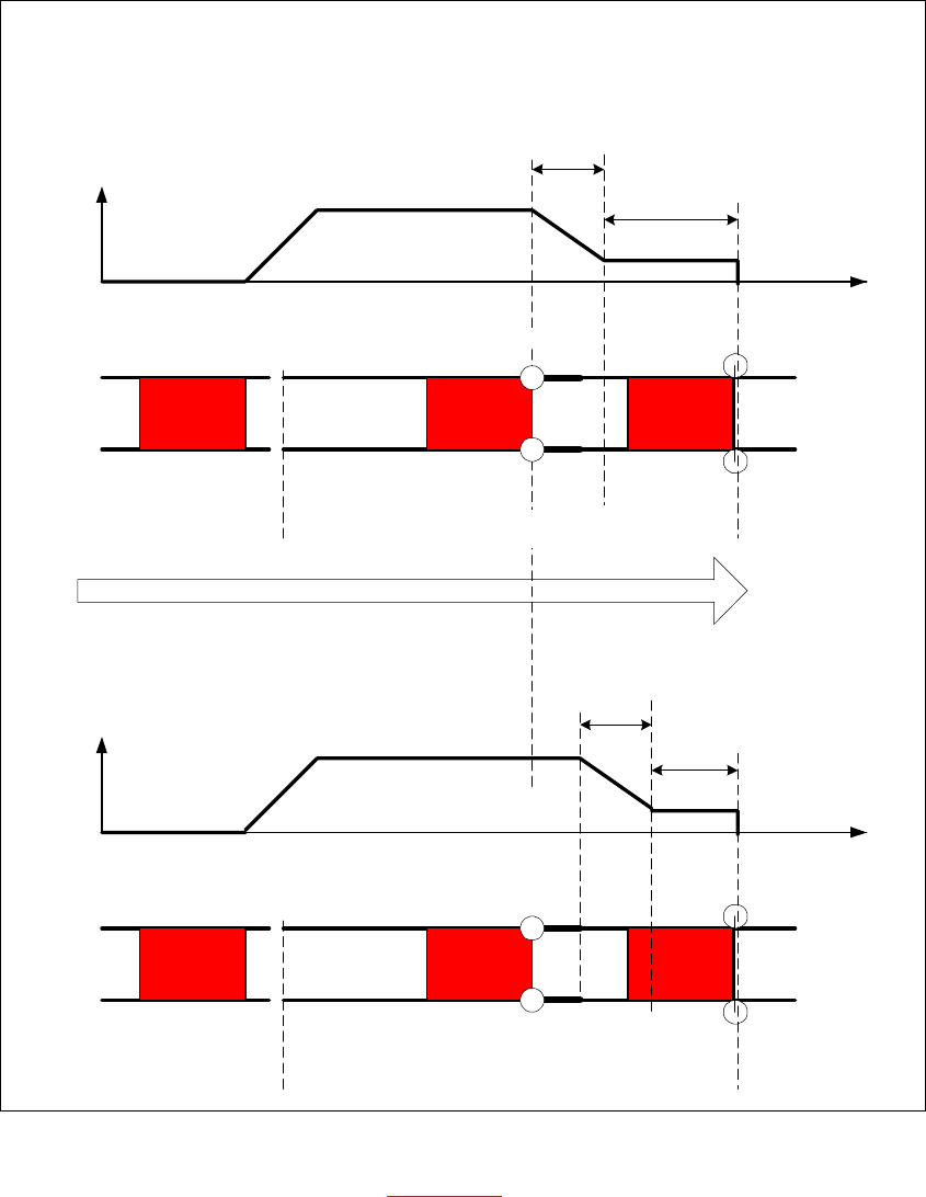
Fig. 6.14.32 Diagrams v(t), PCB braking procedure
The travel profile to brake the PCB (see Fig. 6.14.32) is initiated at the correct moment to ensure
that the PCB is stopped at the laser light barrier after a maximum of 100ms. The automatic learn-
ing process at the beginning of the travel profile ensures that the stopper position is reached in a
constant time, irrespective of the PCB weight. The transport time remains constant.
Direction of PCB transport
Time (t)
< 100 ms
Light barrier
Laser
Travel profile
braking process
Start End
Placement areaInput belt
2nd board
Time (t)
Speed (v)
150 ms
Laser
Travel profile
braking process
Start End
Input belt
1st board
Speed (v)
Placement area
Light barrier
6 Modular PCB conveyor system Service Manual HS-60
6.15 Checks to be performed after mechanical work on the conveyor system 03/2003 US Issue
226
6.15 Checks to be performed after mechanical work on
the conveyor system
DANGER
Please observe the safety instructions in Chapter 2.
Æ Check the distance between the top edge of the conveyor belt and the top of the guide rail.
This measurement should be 6 mm.
Æ Check the distance between the top edge of the conveyor belt and the top of the guide rail at
the clamping sensor.
This measurement should be 5.8 mm.
Æ Check the distance between the actuator clamping device (lifting table) and the top edge of the
belt.
This measurement should be 94.2 mm for the HS-60.
This measurement should be 74.2 mm for the S-27 HM.
Æ Check the distance between the actuator clamping device (lifting table) and the top edge of the
belt at the clamping sensor.
This measurement should be 94.4 mm for the HS-60.
This measurement should be 74.2 mm for the S-27 HM
TIP
Move one PCB into the placement area and clamp the PCB in place. Now measure the distance
between the top edge of the lifting table (rubber stop) and the bottom edge of the PCB. This height
should be exactly 94 mm for the HS-60 and 74 mm for the S-27 HM.
NOTE
The actuator under the clamping sensor must be mounted 0.2 - 0.3 mm lower to guarantee reliable
actuation of the clamping sensor.