Service Manual HS60.pdf - 第98页
4 G ant ri es HS- 6 0 S erv ice Ma nu al 4. 2 S tru ct ure of th e ga ntry 03/ 200 3 US I ssue 96 4 Fig . 4 .2 - 4 T raili ng cab le f or gant ry 1 an d 3 Key (1) Trailin g ca b le (2 ) X /Y d is tr ib u tor (3) Primary …
HS-60 Service Manual 4 Gantries
03/2003 US Issue 4.2 Structure of the gantry
95
The seven power cables take the form of flexible ribbon cables, four of which are needed for the
collect&place head. They run beneath the cover in the machine frame (see item 1 in Fig. 4.2 - 5
),
between the head board on the head mount and the gantry board. 4
4
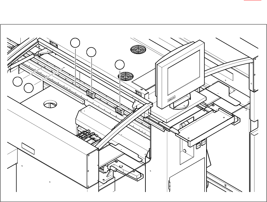
Fig. 4.2 - 3 Y-axis of the gantry
Key
(1) Shuttles of the recirculating ball screw unit for the Y-axis
(2) Guide rail of the recirculating ball screw unit for the Y-axis
(3) Secondary part of the linear drive for the Y-axis (permanent magnets)
(4) Scale for the Y-axis
4
4
3
1
1
2
4 Gantries HS-60 Service Manual
4.2 Structure of the gantry 03/2003 US Issue
96
4
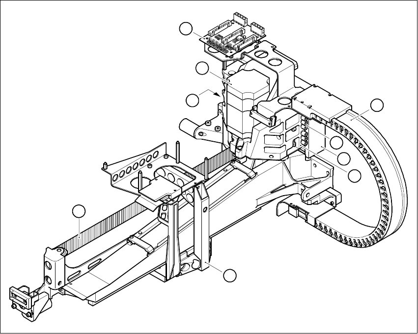
Fig. 4.2 - 4 Trailing cable for gantry 1 and 3
Key
(1) Trailing cable
(2) X/Y distributor
(3) Primary part of the linear drive
(4) Head mount
(5) Three-phase AC motor for the X-axis
(6) Toothed belt for the X-axis
(7) Compressed air inlet couplings
(8) Compressed air outlet coupling
(9) Motor bracket
6
5
4
1
2
3
8
9
7
HS-60 Service Manual 4 Gantries
03/2003 US Issue 4.2 Structure of the gantry
97
4
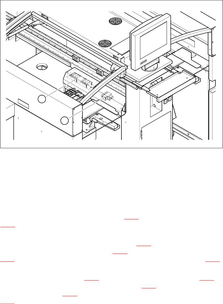
Fig. 4.2 - 5 Position of the gantry and compressed air distributors
Key
(1) Gantry distributor
(2) Compressed air distributor
4
The other three ribbon cables supply power and transmit control signals for the gantry axis drives.
They connect the gantry distributor (see item 1 in Fig. 4.2 - 5
) to the X/Y distributor (item 2 in Fig.
4.2 - 4
). 4
The gantry is supplied with compressed air via seven compressed air hoses. The lines are con-
nected to the compressed air distributor (see item 2 in Fig. 4.2 - 5
). They run in the trailing cable
and end at the inlet couplings (see item 7 in Fig. 4.2 - 4
) on the motor bracket (see item 9 in Fig.
4.2 - 4
). Seven compressed air lines continue from the outlet couplings (see item 8 in Fig. 4.2 - 4)
to the collect&place head. 4
The X-axis motor (see item 5 in Fig. 4.2 - 4
) moves the head mount (see item 4 in Fig. 4.2 - 4) in
the x direction with the aid of a toothed belt (see item 6 in Fig. 4.2 - 4
). The mount is fixed to three
shuttles (see item 1 in Fig. 4.2 - 6
) on the two recirculating ball screw units (see item 2 in Fig.
4.2 - 6
) on the underside of the gantry. This layout guarantees that movement of the X-axis is both
precise and generates very little friction. 4
1
2