Service Manual HS60.pdf - 第82页
3 Pow er S up ply H S-6 0 S erv ic e Manu al 3. 7 M e as ur ing vol ta ge s on th e p o wer su pp ly unit 03/ 200 3 US I ssue 80 3 F ig. 3. 7 - 2 P owe r s up pl y un it - po s iti on of the r ecti fie rs Recti fier Inpu…
HS-60 Service Manual 3 Power Supply
03/2003 US Issue 3.7 Measuring voltages on the power supply unit
79
3.7.5 Measuring voltages at rectifiers V1 to V8
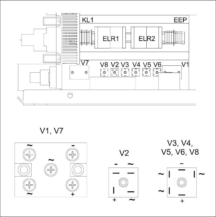
The following diagram shows the position of rectifiers V1 to V8 and their terminal assignments. 3
To take measurements on rectifiers V1 and V7, you must first remove the perspex safety panel.3
RISK OF DEATH BY ELECTRIC SHOCK 3
Æ Switch the placement system off at the main switch.
Æ Disconnect the placement system from the power supply.
Æ Wait approximately 1 minute until the residual voltages have dropped to a safe level (electro-
lytic capacitor C1).
Æ Loosen the two M5 fillister head screws on rectifiers V1 and V7.
Æ Remove the perspex safety panel.
Æ Switch the placement system on and start it up.
Æ Measure the voltages.
3
PLEASE NOTE: The placement system must have started, otherwise there will be no AC volt-
age (3 x 140 VAC) at rectifier V1. V1 uses the 3 x 140 VAC to generate the 200 VDC supply volt-
age for the servo amplifiers of the gantry axes and 100 VDC for the servo amplifiers of the star
axes. These 100 VDC and 4 VDC supplies are fed to the AC voltage inputs of rectifier V2. Rectifier
V2 serves to "OR" the 4 VDC and 100 VDC supplies. If the placement system has not started, only
4 VDC will be present at the positive pole of rectifier V2. 3
3
3 Power Supply HS-60 Service Manual
3.7 Measuring voltages on the power supply unit 03/2003 US Issue
80
3
Fig. 3.7 - 2 Power supply unit - position of the rectifiers
Rectifier Input Output
V1 3 x 140 VAC 200 VDC
V2 100 VDC 100 VDC
V3 3 x 5 VAC 4 VDC
V4 3 x 24 VAC 30 VDC
V5 3 x 25 VAC 40 VDC
V6 3 x 6 VAC 10 VDC
V7 3 x 38 VAC 52 VDC
V8 3 x 20 VAC 30 VDC
HS-60 Service Manual 3 Power Supply
03/2003 US Issue 3.7 Measuring voltages on the power supply unit
81
PLEASE NOTE: Remember to replace the perspex safety panels over rectifiers V1 and V7
when the measurements are complete. 3
RISK OF DEATH BY ELECTRIC SHOCK 3
Æ Switch the placement system off at the main switch.
Æ Disconnect the placement system from the power supply.
Æ Wait approximately 1 minute until the residual voltages have dropped to a safe level (electro-
lytic capacitor C1).
Æ Attach the perspex safety panel and fix in place with the M5 fillister head screws.
CAUTION
Do not overtighten the fillister head screws. The perspex panel might break. 3
3.7.6 Measuring voltages at transformer T1
3.7.6.1 Primary side of transformer T1
The transformer can be connected to the following main power supplies: 3
3 x 230 VAC for the "on-board electrical system" is drawn at terminals 1U5, 1V5 and 1W5. This is
used to supply the PC and the monitor. 3
3
Voltage Terminals
3 x 204 VAC (U. S. A.) ± 5 %, 50/60 Hz 1U6, 1V6, 1W6
3 x 230 VAC ± 5 %, 50/60 Hz 1U5, 1V5, 1W5
3 x 380 VAC ± 5 %, 50/60 Hz 1U4, 1V4, 1W4
3 x 400 VAC (Europe) ± 5 %, 50/60 Hz 1U3, 1V3, 1W3
3 x 415 VAC ± 5 %, 50/60 Hz 1U1, 1V1, 1W1