Service Manual HS60.pdf - 第76页
3 Pow er S up ply H S-6 0 S erv ic e Manu al 3.6 D esc ripti on of t h e power supp ly func tion s 03/ 200 3 US I ssue 74 If one of the S ta rt buttons is p ressed, the SSK swi tches and th e gr een LEDs for c h annel 1 …
HS-60 Service Manual 3 Power Supply
03/2003 US Issue 3.6 Description of the power supply functions
73
3.6 Description of the power supply functions
The placement system cannot be used in placement mode until all the supply voltages have been
enabled by the protective circuit. The following conditions must also be fulfilled: 3
– All four component change-over tables must be docked.
– All covers must be closed.
– Both emergency stop push-buttons must be released.
– All four component flaps over the component tables must be closed.
– The software enable signal must have been sent.
The enable signal is then sent to contactor SZ4 in the power supply unit via port 2 (X2dm) of CAN
input/output module 1 in sector 4 of the distribution board (see block diagram "Distribution board,
sector 4, 00336153-XXXXXXTD3 in the detailed circuit diagrams). 3
3
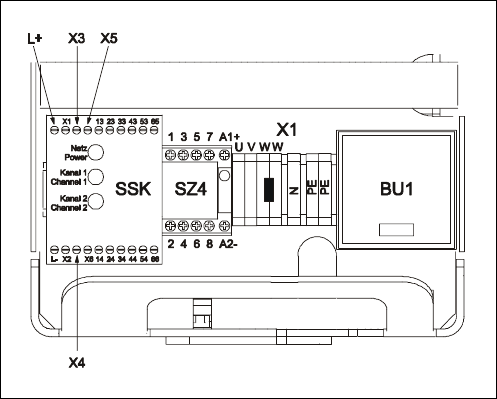
Fig. 3.6 - 1 Power supply unit - partial front view
Contactor SZ4 switches 24 VDC to 3
– L+ on the combined contactor/protective device SSK
– the Start button at X4 of the SSK and
– the emergency stop loop at X3 and X5 on the SSK.
If 24 V is present at L+ on the SSK, the green "Power" LED on the SSK will light up. The message
"M ready" is returned to the computer via port 1 (X1dm) of the CAN input/output module 1 in sector
4 of the distribution board. If the safety loop is closed (covers closed, emergency stop button not
pressed), 24 V is sent to terminals X3 and X5 on the SSK. 3
3 Power Supply HS-60 Service Manual
3.6 Description of the power supply functions 03/2003 US Issue
74
If one of the Start buttons is pressed, the SSK switches and the green LEDs for channel 1 and
channel 2 light up. The five normally open contacts on the SSK switch five independent circuits
(see HS-60 power supply, 00336145-xxxxxxLD4, in the detailed circuit diagrams): 3
– Normally open contact 13-14 actuates SZ2, SZ3 and SZ 23.
SZ2 and SZ3 switch through the 200 VDC and 100 VDC link circuit voltages for the servo
amplifiers of the x, y and star axes. SZ23 switches the current limitation. 3
– Electronic load disconnecting relay ELR1 switches the 3 x 230 VAC operating voltage for
lifting tables 1 and 2 of conveyor 1,
– The optional relay ELR2 switches through the voltage for lifting tables 3 and 4 of conveyor 2.
– An auxiliary contact on contactor SZ23 sends a 24 V signal in the form of an "M_controller
ON" message to CAN input/output module 1 (X1dm) and in the form of a "ServoEnable"
message to the servo unit.
– Normally open contact 23-24 switches the 40 VDC operating voltage to the component ta-
bles.
– Normally open contact 33-34 switches through the 24 VDC operating voltage to the used
tape cutter.
– Normally open contacts 43-44 and 53-54 are provided for the safety loops of external mod-
ules.

HS-60 Service Manual 3 Power Supply
03/2003 US Issue 3.7 Measuring voltages on the power supply unit
75
3.7 Measuring voltages on the power supply unit
3.7.1 Safety instructions
DANGER The placement system is supplied with 3 x 400 VAC
(3 x 204 VAC / 3 x 230 VAC / 3 x 380 VAC / 3 x 415 VAC) ± 5 %, 50/60 Hz main voltage. 3
– Consequently, parts of the system carry potentially lethal voltages, even when switched off at
the main switch.
– Incorrect handling of the placement system can therefore result in death or severe injury or
considerable damage to equipment.
– Measurements and repairs must always be carried out by appropriately qualified personnel.
– Always follow the safety instructions in section 2 of this manual.
– Always follow the applicable accident prevention and VDE regulations (particularly DIN EN 60
204 part 1) or the regulations specific to your country.
– Before starting any repairs, switch off at the main switch and disconnect the placement system
from the main power supply.
– Secure the system to prevent it being switched on again. If these instructions are not followed,
it is possible to touch live parts, which could result in death or severe injury.
3.7.2 Tools and equipment required
– Digital voltmeter, class 1.5
3
– Test cable with test probes or terminals
– HS-60 detailed circuit diagrams, item no. 00193426-01
– DIN 911 Allen key, size 6
– 3 mm key, double-bit, DIN 43668-J33, item no. 00304191-01
Measuring ranges
AC voltage 750 V
Alternating current 40 A
DC voltage 300 V
Direct current 30 A
Resistance 200 Ohm - 20 MOhm