MIL-STD-202H.pdf - 第135页
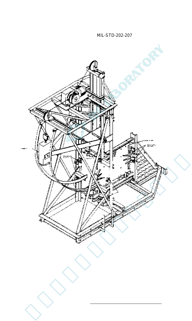
MI L - S TD - 202 - 207 FI GURE 1 . High - impact shock - tes ting apparat us . 3 北测(上海)电子科技有限公 司 联系方式:xuyj@beice-sh.com 13917165676
MIL-STD-202-207
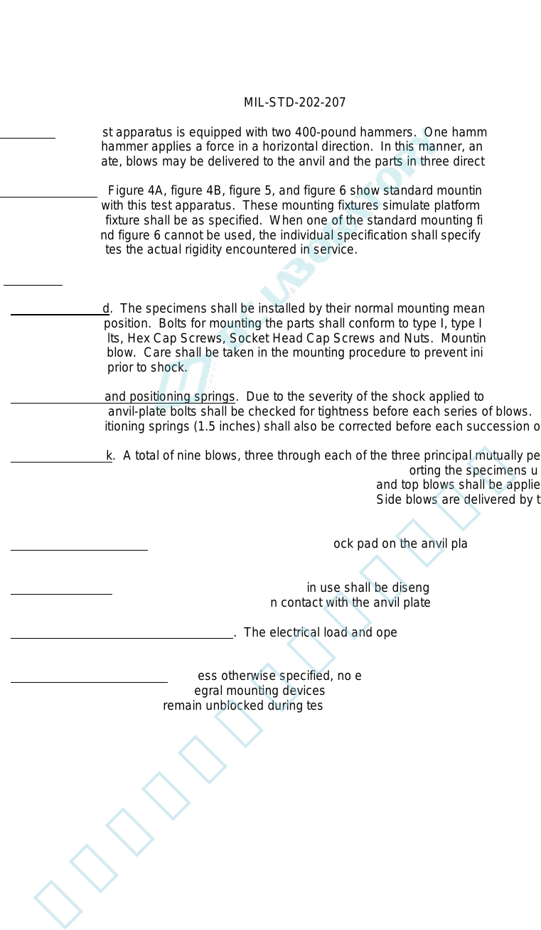
4.4 Hammers. The test apparatus is equipped with two 400-pound hammers. One hammer renders a blow by a
vertical drop. The other hammer applies a force in a horizontal direction. In this manner, and by changing the
orientation of the anvil plate, blows may be delivered to the anvil and the parts in three directions.
4.5 Mounting fixtures. Figure 4A, figure 4B, figure 5, and figure 6 show standard mounting fixtures that shall be
used when testing parts with this test apparatus. These mounting fixtures simulate platform and panel mountings.
The applicable mounting fixture shall be as specified. When one of the standard mounting fixtures shown on figure
4A, figure 4B, figure 5, and figure 6 cannot be used, the individual specification shall specify a mounting fixture or
adapter which approximates the actual rigidity encountered in service.
4.6. Procedure.
4.6.1 Mounting method. The specimens shall be installed by their normal mounting means on the mounting fixture
in their normal operating position. Bolts for mounting the parts shall conform to type I, type II, or type III, grade 2, of
MIL-DTL-1222, Studs, Bolts, Hex Cap Screws, Socket Head Cap Screws and Nuts. Mounting bolts shall be checked
for tightness before each blow. Care shall be taken in the mounting procedure to prevent initial stresses being
applied to the specimens prior to shock.
4.6.2 Anvil-plate bolts and positioning springs. Due to the severity of the shock applied to the anvil plate by a
series of three blows, the anvil-plate bolts shall be checked for tightness before each series of blows. The spacing
between stops of the positioning springs (1.5 inches) shall also be corrected before each succession of blows.
4.6.3 Direction of shock. A total of nine blows, three through each of the three principal mutually perpendicular
axes for the heights indicated in 4.6.4, shall be delivered to the anvil plate supporting the specimens under test.
Direction of the shock shall be, in order, to the back, top, and side. Back and top blows shall be applied with the anvil
plate located to receive blows from the horizontal and vertical hammers. Side blows are delivered by the horizontal
hammer contacting the end shock pad of the anvil plate (see 4.3).
4.6.4 Height of hammer drops. The hammer shall strike the shock pad on the anvil plate, in sequence, from
heights of 1 foot, 3 feet, and 5 feet.
4.6.5 Hammer supports. During the test, the hammer not in use shall be disengaged from the lifting cable and
supported so that the hammer and its support are not in contact with the anvil plate.
4.6.6 Electrical load and operating conditions. The electrical load and operating conditions applied to the
specimens shall be as specified.
4.6.7 External resilient mountings. Unless otherwise specified, no external resilient mountings associated with the
specimen being tested shall be used. Integral mounting devices and external resilient mountings (if specified)
associated with the specimen shall remain unblocked during tests.
2
北测(上海)电子科技有限公司
联系方式:xuyj@beice-sh.com 13917165676
MIL-STD-202-207
FIGURE 1. High-impact shock-testing apparatus.
3
北测(上海)电子科技有限公司
联系方式:xuyj@beice-sh.com 13917165676
MIL-STD-202-207
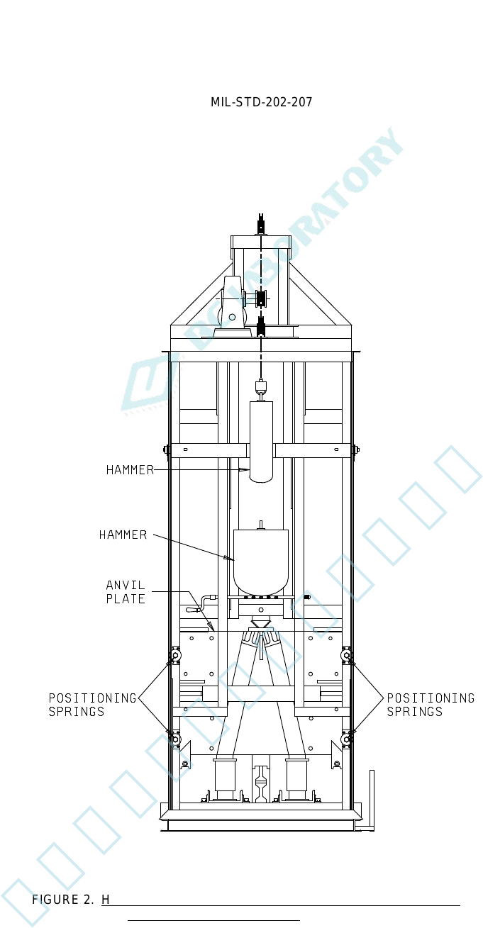
FIGURE 2. High-impact shock-testing apparatus (backview) with anvil plate
located for back and top blows.
4
北测(上海)电子科技有限公司
联系方式:xuyj@beice-sh.com 13917165676