MIL-STD-202H.pdf - 第272页
MI L - S TD - 202 - 308 T ABL E 1 . S t and ar d o per at i ng c ond i t i o ns . | | | | | Res istance | R es i s t or s 1 / 2 w at t and hi g her | R e s i s to r s 1 /4 , 1 / 8 , and 1/10 watt | | | | | | | | | | | Re…
MIL-STD-202-308
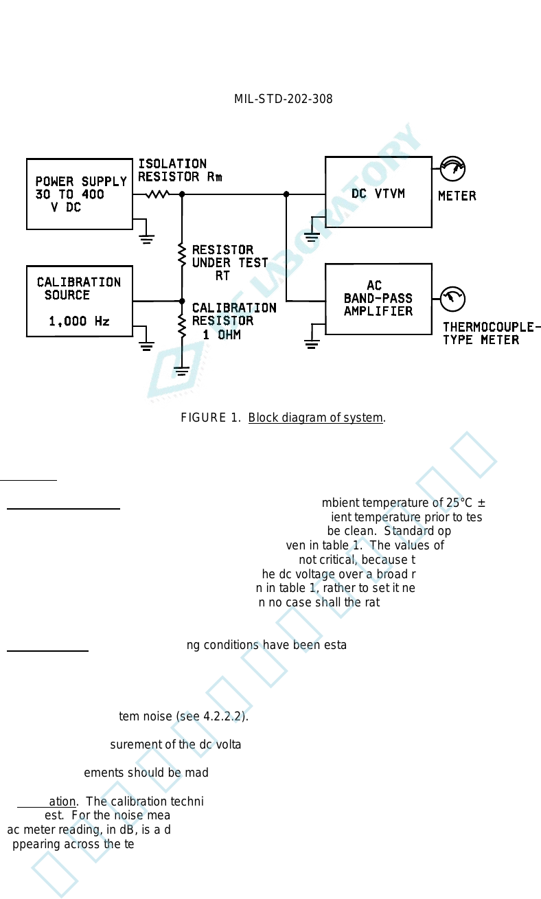
FIGURE 1. Block diagram of system.
4.2. Procedure.
4.2.1 Operating conditions. The test shall be performed at an ambient temperature of 25°C ±2°C, unless otherwise
specified. The specimen under test shall be stabilized at room ambient temperature prior to test. No special
preparations of the specimen are required other than that its leads be clean. Standard operating conditions, based
on the resistance value of the specimen to be tested, are given in table 1. The values of the isolation resistor, Rm,
and the dc voltage, V, should be observed, although they are not critical, because the index is reasonably
independent of the values of the isolation resistor and the dc voltage over a broad range. Therefore, it is not
necessary to obtain the exact value of dc voltage given in table 1, rather to set it near the value, and to read carefully
and record its value at the time of the measurement. In no case shall the ratings of the resistor under test be
exceeded.
4.2.2 Measurements. After the operating conditions have been established, the measurement operation shall be
performed in three steps, as follows:
(1) Calibration (see 4.2.2.1).
(2) Measurement of system noise (see 4.2.2.2).
(3) Simultaneous measurement of the dc voltage and the resulting total noise (see 4.2.2.3).
Generally, the measurements should be made in the order listed. The precautions in 1.2 should be observed.
4.2.2.1 Calibration. The calibration technique (see 4.1.1.3) standardizes the gain of the ac system for the particular
resistor under test. For the noise measurements in steps 2 and 3 which follow, the sum of the ac attenuator setting
and the ac meter reading, in dB, is a direct indication of the noise present in terms of an "open-circuit" rms noise
voltage appearing across the terminals of the resistor under test.
3
北测(上海)电子科技有限公司
联系方式:xuyj@beice-sh.com 13917165676
MIL-STD-202-308
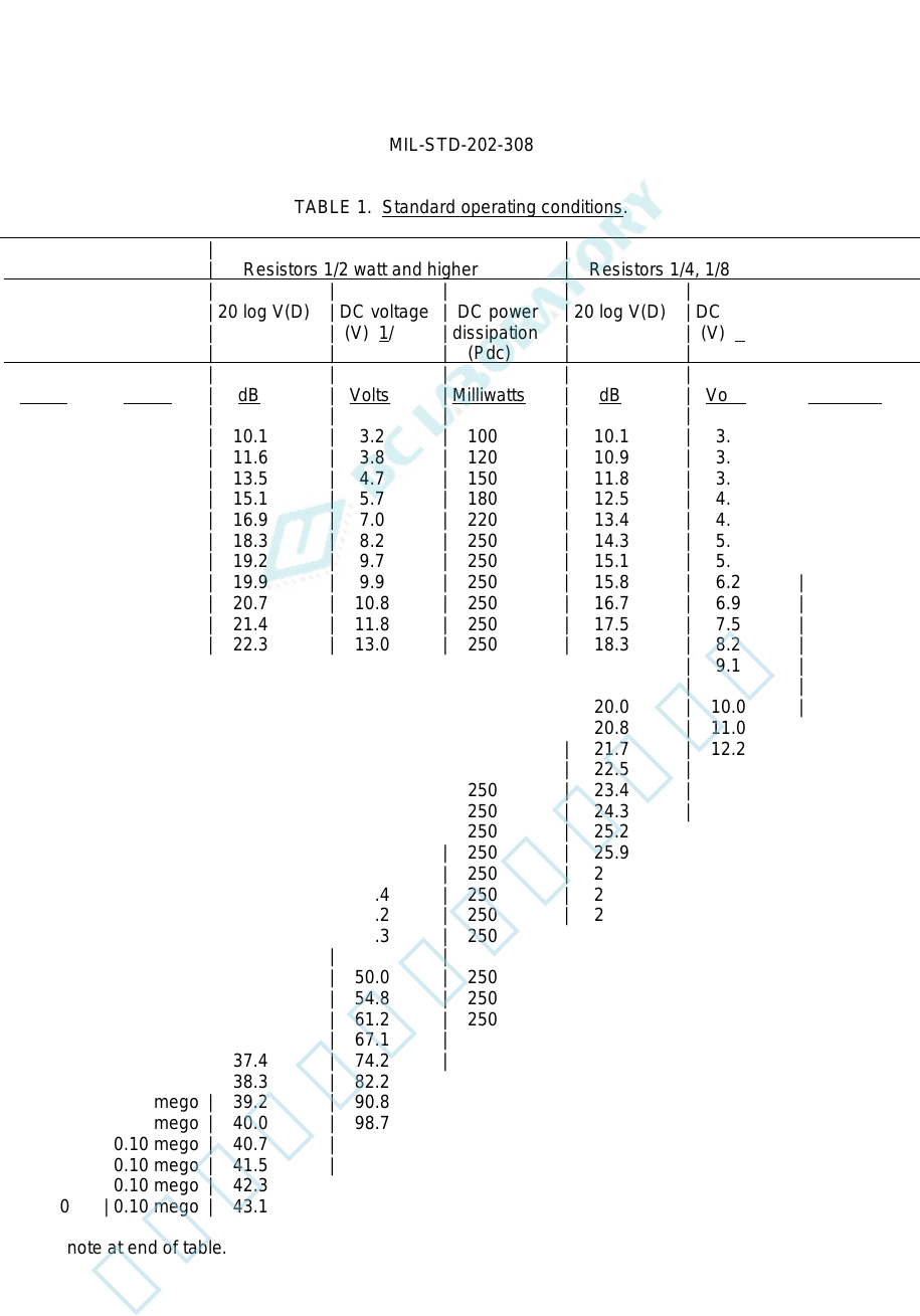
TABLE 1. Standard operating conditions.
| | | |
| Resistance | Resistors 1/2 watt and higher | Resistors 1/4, 1/8, and 1/10 watt |
| | | | | | | | |
| Resistor | Isolation | 20 log V(D) | DC voltage | DC power | 20 log V(D) | DC voltage | DC power |
| under | resistor | | (V) 1/ | dissipation | | (V) 1/ | dissipation |
| test (Rt) | (Rm) | | | (Pdc) | | | (Pdc) |
| | | | | | | | |
| Ohms | Ohms | dB | Volts | Milliwatts | dB | Volts | Milliwatts |
| | | | | | | | |
| 100 | 1,000 | 10.1 | 3.2 | 100 | 10.1 | 3.2 | 100 |
| 120 | 1,000 | 11.6 | 3.8 | 120 | 10.9 | 3.5 | 100 |
| 150 | 1,000 | 13.5 | 4.7 | 150 | 11.8 | 3.9 | 100 |
| 180 | 1,000 | 15.1 | 5.7 | 180 | 12.5 | 4.2 | 100 |
| 220 | 1,000 | 16.9 | 7.0 | 220 | 13.4 | 4.7 | 100 |
| 270 | 1,000 | 18.3 | 8.2 | 250 | 14.3 | 5.2 | 100 |
| 330 | 1,000 | 19.2 | 9.7 | 250 | 15.1 | 5.7 | 100 |
| 390 | 1,000 | 19.9 | 9.9 | 250 | 15.8 | 6.2 | 100 |
| 470 | 1,000 | 20.7 | 10.8 | 250 | 16.7 | 6.9 | 100 |
| 560 | 1,000 | 21.4 | 11.8 | 250 | 17.5 | 7.5 | 100 |
| 680 | 1,000 | 22.3 | 13.0 | 250 | 18.3 | 8.2 | 100 |
| 820 | 1,000 | 23.1 | 14.3 | 250 | 19.2 | 9.1 | 100 |
| | | | | | | | |
| 1,000 | 1,000 | 24.0 | 15.8 | 250 | 20.0 | 10.0 | 100 |
| 1,200 | 1,000 | 24.8 | 17.3 | 250 | 20.8 | 11.0 | 100 |
| 1,500 | 1,000 | 25.8 | 19.4 | 250 | 21.7 | 12.2 | 100 |
| 1,800 | 1,000 | 26.6 | 21.2 | 250 | 22.5 | 13.4 | 100 |
| 2,200 | 1,000 | 27.4 | 23.4 | 250 | 23.4 | 14.8 | 100 |
| 2,700 | 10,000 | 28.3 | 26.0 | 250 | 24.3 | 16.4 | 100 |
| 3,300 | 10,000 | 29.2 | 28.7 | 250 | 25.2 | 18.2 | 100 |
| 3,900 | 10,000 | 29.9 | 31.2 | 250 | 25.9 | 19.7 | 100 |
| 4,700 | 10,000 | 30.8 | 34.3 | 250 | 26.7 | 21.7 | 100 |
| 5,600 | 10,000 | 31.5 | 37.4 | 250 | 27.5 | 23.7 | 100 |
| 6,800 | 10,000 | 32.3 | 41.2 | 250 | 28.3 | 26.1 | 100 |
| 8,200 | 10,000 | 33.2 | 45.3 | 250 | 29.1 | 28.6 | 100 |
| | | | | | | | |
| 10,000 | 10,000 | 34.0 | 50.0 | 250 | 30.1 | 32.0 | 100 |
| 12,000 | 10,000 | 34.8 | 54.8 | 250 | 30.9 | 35.0 | 100 |
| 15,000 | 10,000 | 35.8 | 61.2 | 250 | 31.8 | 39.0 | 100 |
| 18,000 | 10,000 | 36.6 | 67.1 | 250 | 32.5 | 42.0 | 100 |
| 22,000 | 10,000 | 37.4 | 74.2 | 250 | 33.4 | 47.0 | 100 |
| 27,000 | 0.10 mego | 38.3 | 82.2 | 250 | 34.3 | 52.0 | 100 |
| 33,000 | 0.10 mego | 39.2 | 90.8 | 250 | 35.1 | 57.0 | 100 |
| 39,000 | 0.10 mego | 40.0 | 98.7 | 250 | 35.8 | 62.0 | 100 |
| 47,000 | 0.10 mego | 40.7 | 108 | 250 | 36.7 | 69.0 | 100 |
| 56,000 | 0.10 mego | 41.5 | 118 | 250 | 37.5 | 75.0 | 100 |
| 68,000 | 0.10 mego | 42.3 | 130 | 250 | 38.3 | 82.0 | 100 |
| 82,000 | 0.10 mego | 43.1 | 143 | 250 | 39.2 | 91.0 | 100 |
See footnote at end of table.
4
北测(上海)电子科技有限公司
联系方式:xuyj@beice-sh.com 13917165676
MIL-STD-202-308
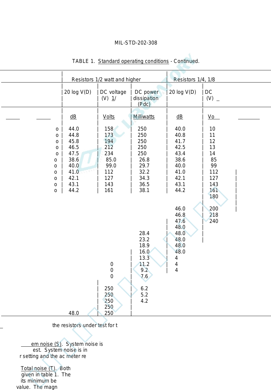
TABLE 1. Standard operating conditions - Continued.
| | | |
| Resistance | Resistors 1/2 watt and higher | Resistors 1/4, 1/8, and 1/10 watt |
| | | | | | | | |
| Resistor | Isolation | 20 log V(D) | DC voltage | DC power | 20 log V(D) | DC voltage | DC power |
| under | resistor | | (V) 1/ | dissipation | | (V) 1/ | dissipation |
| test (Rt) | (Rm) | | | (Pdc) | | | (Pdc) |
| | | | | | | | |
| Ohms | Ohms | dB | Volts | Milliwatts | dB | Volts | Milliwatts |
| | | | | | | | |
| 0.10 mego | 0.10 mego | 44.0 | 158 | 250 | 40.0 | 100 | 100 |
| 0.12 mego | 0.10 mego | 44.8 | 173 | 250 | 40.8 | 110 | 100 |
| 0.15 mego | 0.10 mego | 45.8 | 194 | 250 | 41.7 | 122 | 100 |
| 0.18 mego | 0.10 mego | 46.5 | 212 | 250 | 42.5 | 134 | 100 |
| 0.22 mego | 0.10 mego | 47.5 | 234 | 250 | 43.4 | 148 | 100 |
| 0.27 mego | 1.0 mego | 38.6 | 85.0 | 26.8 | 38.6 | 85.0 | 26.8 |
| 0.33 mego | 1.0 mego | 40.0 | 99.0 | 29.7 | 40.0 | 99.0 | 29.7 |
| 0.39 mego | 1.0 mego | 41.0 | 112 | 32.2 | 41.0 | 112 | 32.2 |
| 0.47 mego | 1.0 mego | 42.1 | 127 | 34.3 | 42.1 | 127 | 34.3 |
| 0.56 mego | 1.0 mego | 43.1 | 143 | 36.5 | 43.1 | 143 | 36.5 |
| 0.68 mego | 1.0 mego | 44.2 | 161 | 38.1 | 44.2 | 161 | 38.1 |
| 0.82 mego | 1.0 mego | 45.1 | 180 | 39.5 | 45.1 | 180 | 39.5 |
| | | | | | | | |
| 1.0 mego | 1.0 mego | 46.0 | 200 | 40.0 | 46.0 | 200 | 40.0 |
| 1.2 mego | 1.0 mego | 46.8 | 218 | 39.6 | 46.8 | 218 | 39.6 |
| 1.5 mego | 1.0 mego | 47.6 | 240 | 38.4 | 47.6 | 240 | 38.4 |
| 1.8 mego | 1.0 mego | 48.0 | 250 | 34.7 | 48.0 | 250 | 34.7 |
| 2.2 mego | 1.0 mego | 48.0 | 250 | 28.4 | 48.0 | 250 | 28.4 |
| 2.7 mego | 1.0 mego | 48.0 | 250 | 23.2 | 48.0 | 250 | 23.2 |
| 3.3 mego | 1.0 mego | 48.0 | 250 | 18.9 | 48.0 | 250 | 18.9 |
| 3.9 mego | 1.0 mego | 48.0 | 250 | 16.0 | 48.0 | 250 | 16.0 |
| 4.7 mego | 1.0 mego | 48.0 | 250 | 13.3 | 48.0 | 250 | 13.3 |
| 5.6 mego | 1.0 mego | 48.0 | 250 | 11.2 | 48.0 | 250 | 11.2 |
| 6.8 mego | 1.0 mego | 48.0 | 250 | 9.2 | 48.0 | 250 | 9.2 |
| 8.2 mego | 1.0 mego | 48.0 | 250 | 7.6 | 48.0 | 250 | 7.6 |
| | | | | | | | |
| 10 mego | 1.0 mego | 48.0 | 250 | 6.2 | 48.0 | 250 | 6.2 |
| 12 mego | 1.0 mego | 48.0 | 250 | 5.2 | 48.0 | 250 | 5.2 |
| 15 mego | 1.0 mego | 48.0 | 250 | 4.2 | 48.0 | 250 | 4.2 |
| 18 mego | 1.0 mego | 48.0 | 250 | 3.5 | 48.0 | 250 | 3.5 |
| 22 mego | 1.0 mego | 48.0 | 250 | 2.8 | 48.0 | 250 | 2.8 |
1/ DC voltage across the resistors under test for the measurement of total noise.
4.2.2.2 System noise (S). System noise is the background noise present when direct current is not present in the
resistor under test. System noise is indicated after turning off the calibration voltage. The algebraic sum of the ac
attenuator setting and the ac meter reading gives the magnitude of system noise, S, in dB.
4.2.2.3 Total noise (T). Both the dc voltage and the total noise are measured simultaneously. The value of dc
voltage is given in table 1. The application of excessive dc voltage should be avoided by setting the dc voltage
control to its minimum before applying the voltage, and when the voltage is applied, it should be increased to the
desired value. The magnitude of the dc voltage is given by the sum, D, of the dc attenuator setting and the dc meter
reading in dB. D equals 20 log V, where V is the dc voltage, in volts, applied to the terminals of the resistor under
test. The associated noise measurement indicates the total noise present, i.e., the quadratic sum of the system noise
and the current noise. This total noise is indicated by T, in dB.
5
北测(上海)电子科技有限公司
联系方式:xuyj@beice-sh.com 13917165676