MIL-STD-202H.pdf - 第148页
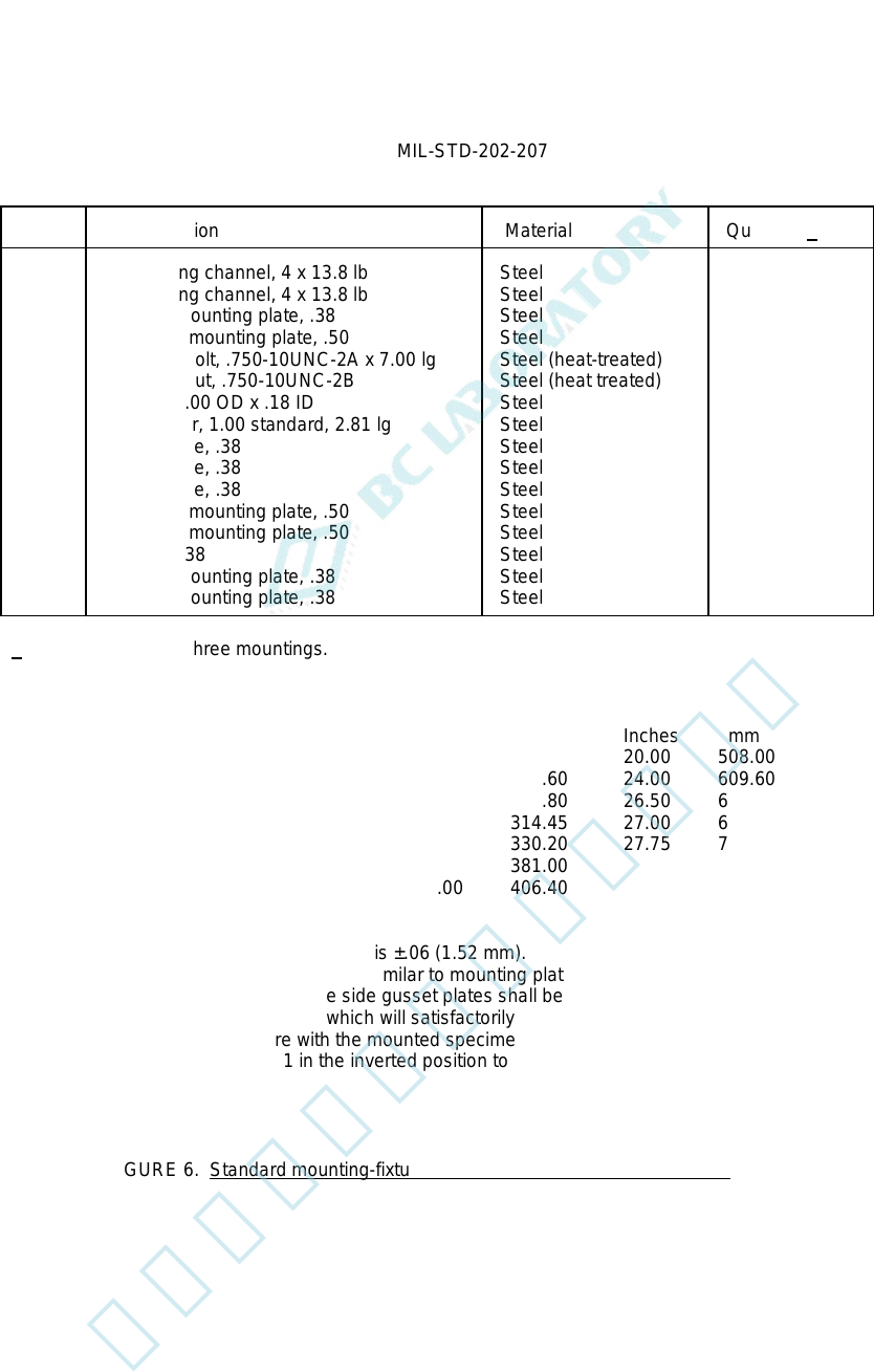
MI L - S TD - 202 - 207 Item Desc rip t i on M at er i al Q u antity 1 / 1 2 3 4 5 6 7 8 9 10 11 12 13 14 15 16 Car buildi n g c han nel , 4 x 13. 8 l b Car buildi n g c han nel , 4 x 13. 8 l b Aux iliary m ount i ng pl …
MIL-STD-202-207
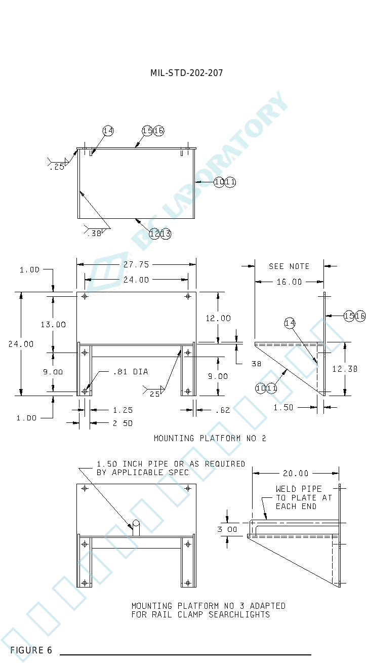
FIGURE 6. Standard mounting-fixtures for deck or platform mounted parts - Continued.
15
北测(上海)电子科技有限公司
联系方式:xuyj@beice-sh.com 13917165676
MIL-STD-202-207
Item
Description
Material
Quantity 1/
1
2
3
4
5
6
7
8
9
10
11
12
13
14
15
16
Car building channel, 4 x 13.8 lb
Car building channel, 4 x 13.8 lb
Auxiliary mounting plate, .38
Horizontal mounting plate, .50
Hex head bolt, .750-10UNC-2A x 7.00 lg
Hex head nut, .750-10UNC-2B
Washer, 2.00 OD x .18 ID
Pipe spacer, 1.00 standard, 2.81 lg
Gusset plate, .38
Gusset plate, .38
Gusset plate, .38
Horizontal mounting plate, .50
Horizontal mounting plate, .50
Stiffener, .38
Auxiliary mounting plate, .38
Auxiliary mounting plate, .38
Steel
Steel
Steel
Steel
Steel (heat-treated)
Steel (heat treated)
Steel
Steel
Steel
Steel
Steel
Steel
Steel
Steel
Steel
Steel
1
1
1
1
6
6
12
6
2
2
2
1
1
4
1
1
1/ Quantities are for three mountings.
Inches mm Inches mm Inches mm Inches mm
.18 4.57 1.25 31.75 9.00 228.60 20.00 508.00
.25 6.35 1.50 38.10 11.00 279.60 24.00 609.60
.38 9.65 2.00 50.80 12.00 304.80 26.50 673.10
.50 12.70 2.50 63.50 12.38 314.45 27.00 685.80
.62 15.75 2.81 71.73 13.00 330.20 27.75 704.85
.81 20.57 3.00 76.20 15.00 381.00
1.00 25.40 7.00 177.80 16.00 406.40
NOTES:
1. Unless otherwise specified, tolerance is ±.06 (1.52 mm).
2. Mounting platform number 3 shall be similar to mounting platform number 2 with the exception of the
horizontal mounting plate and the side gusset plates shall be increased to 22.00 inches (558.80 mm).
3. The smallest mounting platform which will satisfactorily accommodate the specimen shall be selected.
4. If the deep gussets interfere with the mounted specimen, the extra bolt holes shall be used in bolting of
mounting platform number 1 in the inverted position to the four lower bolt holes of the anvil plate.
FIGURE 6. Standard mounting-fixtures for deck or platform mounted parts - Continued.
16
北测(上海)电子科技有限公司
联系方式:xuyj@beice-sh.com 13917165676
MIL-STD-202-207
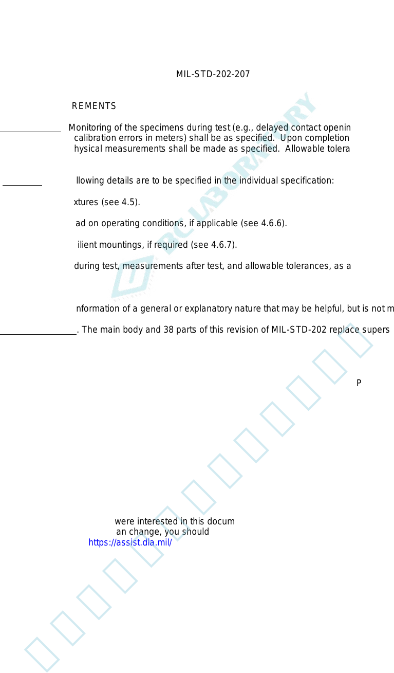
5. DETAILED REQUIREMENTS
5.1 Measurements. Monitoring of the specimens during test (e.g., delayed contact opening of relays, momentary
stopping of dynamotors, calibration errors in meters) shall be as specified. Upon completion of the required number
of blows, electrical and physical measurements shall be made as specified. Allowable tolerances shall be as
specified.
5.2. Summary. The following details are to be specified in the individual specification:
a. Mounting fixtures (see 4.5).
b. Electrical load on operating conditions, if applicable (see 4.6.6).
c. External resilient mountings, if required (see 4.6.7).
d. Monitoring during test, measurements after test, and allowable tolerances, as applicable (see 5.1).
6. NOTES
(This section contains information of a general or explanatory nature that may be helpful, but is not mandatory.)
6.1 Supersession data. The main body and 38 parts of this revision of MIL-STD-202 replace superseded MIL-STD-
202.
Custodians: Preparing activity:
Army - CR DLA – CC
Navy - EC
Air Force - 85 (Project 59GP-2015-021)
DLA - CC
Review activities:
Army - AR, AT, AV, CR4, MI, SM, TE
Navy - AS, OS, SH
Air Force - 19, 99
NSA - NS
NOTE: The activities listed above were interested in this document as of the date of this document. Since
organizations and responsibilities can change, you should verify the currency of the information above using the
ASSIST Online database at https://assist.dla.mil/
17
北测(上海)电子科技有限公司
联系方式:xuyj@beice-sh.com 13917165676