MIL-STD-202H.pdf - 第287页
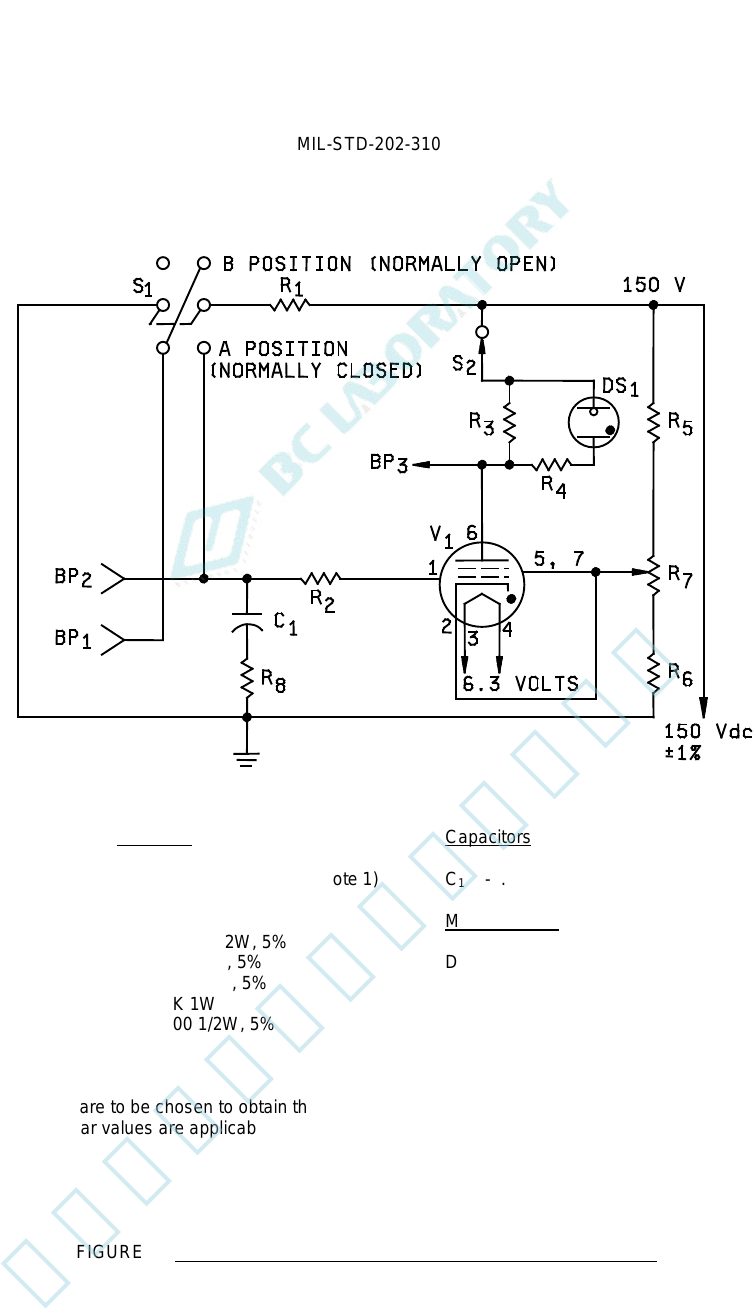
MI L - S TD - 202 -3 10 Resistors C apac i t or s R 1 - 35K 1/2 W , 1% ( see n ot e 1) C 1 - . 0022 µ F, 600 VDC W (see not e 1) R 2 - 27K 1/2 W , 5% R 3 - 47K 1 W , 5% M iscellan eous R 4 - 200K 1/ 2 W , 5 % R 5 - 70K 1…
MIL-STD-202-310
4.2. Test systems.
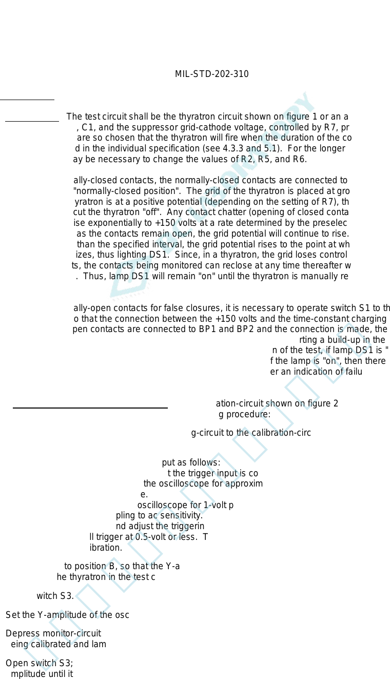
4.2.1 Test-circuit A. The test circuit shall be the thyratron circuit shown on figure 1 or an approved equivalent
circuit. The values for R1, C1, and the suppressor grid-cathode voltage, controlled by R7, principally controls the
firing of the thyratron and are so chosen that the thyratron will fire when the duration of the contact-opening exceeds
the time-duration specified in the individual specification (see 4.3.3 and 5.1). For the longer time-durations, such as
above 1 millisecond, it may be necessary to change the values of R2, R5, and R6.
a. To monitor normally-closed contacts, the normally-closed contacts are connected to BP1 and BP2, with
switch S1 in the "normally-closed position". The grid of the thyratron is placed at ground potential. The
cathode of the thyratron is at a positive potential (depending on the setting of R7), thus providing sufficient
negative bias to cut the thyratron "off". Any contact chatter (opening of closed contacts) will cause the grid of
the thyratron to rise exponentially to +150 volts at a rate determined by the preselected time constant of R1
and C1. As long as the contacts remain open, the grid potential will continue to rise. If the contacts remain
"open" for longer than the specified interval, the grid potential rises to the point at which the thyratron
conducts and ionizes, thus lighting DS1. Since, in a thyratron, the grid loses control of conduction as soon as
the tube conducts, the contacts being monitored can reclose at any time thereafter without affecting the
monitoring circuit. Thus, lamp DS1 will remain "on" until the thyratron is manually reset by operation of
switch S2.
b. To monitor normally-open contacts for false closures, it is necessary to operate switch S1 to the "normally-
open position", so that the connection between the +150 volts and the time-constant charging circuit is
"open". When open contacts are connected to BP1 and BP2 and the connection is made, these contacts
"close". At contact closure, voltage is applied to the charging circuit, starting a build-up in the same manner
as described in (a) for normally-closed contacts. At the conclusion of the test, if lamp DS1 is "off", then there
has been a no-chatter interval exceeding the specified duration; if the lamp is "on", then there was at least
one-interval when the specified time-duration was exceeded. After an indication of failure, the thyratron
circuit shall be restarted by operation of switch S2.
4.2.1.1 Calibration procedure for test-circuit A. The calibration-circuit shown on figure 2 may be used to calibrate
the monitoring-circuit shown on figure 1 by using the following procedure:
a. Make the proper connections of the monitoring-circuit to the calibration-circuit as shown, and set switch S1 to
position A.
b. Calibrate the oscilloscope triggering input as follows:
(1) Set switch S4 to position A, so that the trigger input is connected to the Y-axis input of the oscilloscope.
(2) Set the time-base control of the oscilloscope for approximately 20-percent of the time-duration for which
the calibration is being made.
(3) Set the Y-amplitude of the oscilloscope for 1-volt per centimeter.
(4) Set the triggering coupling to ac sensitivity.
(5) Open the switch S3 and adjust the triggering level and stability control so that the trace on the
oscilloscope will trigger at 0.5-volt or less. The closer the trigger-level is to zero, the greater the
accuracy of calibration.
c. Set switch S4 to position B, so that the Y-axis input of the oscilloscope is connected through capacitor C4 to
the plate of the thyratron in the test circuit.
d. Close switch S3.
e. Set the Y-amplitude of the oscilloscope for a usable display, and the time-base as in preceding (b) (2).
f. Depress monitor-circuit reset switch S2 of figure 1 to set the circuit in the "ready" position, i.e., with the circuit
being calibrated and lamp DS1 extinguished.
g. Open switch S3; the observed trace of the oscilloscope should move across the screen at a positive
amplitude until it is deflected downward by the negative pulse created when the thyratron fires. The time
interval between the start of the trace and the negative pulse is the detection time. Adjust R7 of figure 1 to
the time-duration specified in the individual specification.
2
北测(上海)电子科技有限公司
联系方式:xuyj@beice-sh.com 13917165676
MIL-STD-202-310
Resistors Capacitors
R
1
- 35K 1/2W, 1% (see note 1) C
1
- .0022µF, 600 VDCW (see note 1)
R
2
- 27K 1/2W, 5%
R
3
- 47K 1W, 5% Miscellaneous
R
4
- 200K 1/2W, 5%
R
5
- 70K 1W, 5% DS
1
- NE-51
R
6
- 2.4K 1W, 5% S
1
- DPDT
R
7
- 5K 1W S
2
- SPSTNC 125V 1 amp (push)
R
8
- 500 1/2W, 5% V
1
- JAN-5727/2D21W
NOTES:
1. These values are to be chosen to obtain the desired time-duration for the applicable test condition (see 4.3).
These particular values are applicable to 10 microseconds time-duration only.
FIGURE 1. Test-circuit A; monitor circuit for contact-opening and closing.
3
北测(上海)电子科技有限公司
联系方式:xuyj@beice-sh.com 13917165676
MIL-STD-202-310
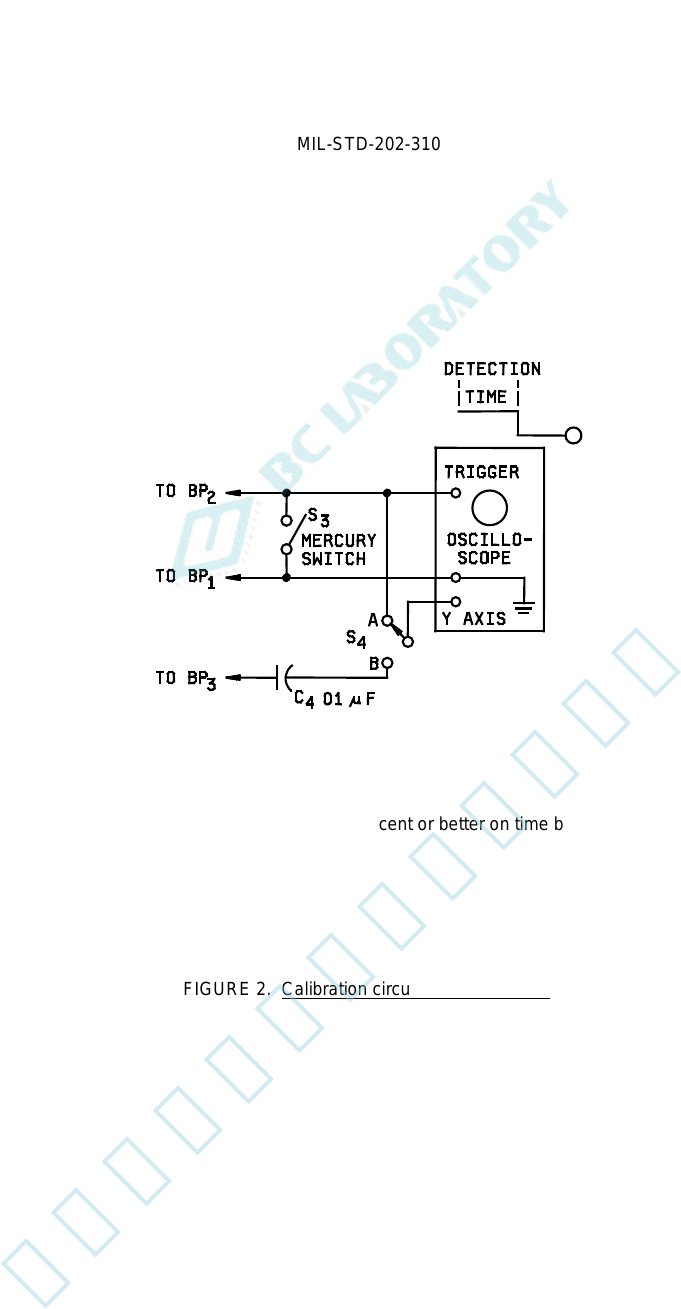
NOTE: The oscilloscope shall have an accuracy of ±3 percent or better on time base and have provision for
external triggering.
FIGURE 2. Calibration circuit for test-circuit A.
4
北测(上海)电子科技有限公司
联系方式:xuyj@beice-sh.com 13917165676