MIL-STD-202H.pdf - 第179页
MI L - S TD - 202 -2 11 4.2 . Procedure . One or m or e of t he f ol l ow i ng t e s t c ond i t i on l et t er s s h al l be s pe c i f i ed i n t he individual spe cification: 4.2 .1 Test c ondition A ( pu l l t e s t …
MIL-STD-202-211
METHOD 211
TERMINAL STRENGTH
1. SCOPE
1.1 Purpose. This test is performed to determine whether the design of the terminals and their method of
attachment can withstand one or more of the applicable mechanical stresses to which they will be subjected during
installation or disassembly in equipment. These stresses must be withstood by the component part without
sustaining damage which would affect either the utility of the terminals or the operation of the component part itself.
Evidence of damage caused by this test may not become evident until subsequent environmental tests are
performed, such as seal, moisture resistance, or life. Procedures are established in this method for testing wire-lead
terminals, flexible-flat-strip or tab-lead terminals, and rigid-type terminals which are threaded or have other
arrangements for attaching conductors. The forces applied consist of direct axial, radial or tension pulls, twist,
bending torsion, and the torque exerted by the application of nuts or screws on threaded terminals. These applied
stresses will disclose poor workmanship, faulty designs, and inadequate methods of attaching terminals to the body
of the part. Other evidence of damage may be disclosed by mechanical distortion of the part, breaking of seals,
cracking of materials surrounding the terminals, or changes in electrical characteristics, such as shorted or
interrupted circuits and changes in resistance values.
2. APPLICABLE DOCUMENTS
This section not applicable to this standard.
3. DEFINTIONS
This section not applicable to this standard.
4. GENERAL REQUIREMENTS
4.1. Test conditions.
4.1.1 Selection. In this method there are five test conditions, A, B, C, D, and E. The selection of test conditions to
perform the terminal-strength test depends on the type of terminal to be tested. The individual specification shall
specify the test condition required. The following is included as a guide to be used, as applicable:
Test condition A: Pull test - also known as a tension or tensile test for terminals. It is usually applicable to
most types of terminals.
Test condition B: Flat-terminal bend test - also known as a bend test. It is applicable to flexible-flat-strip or
tab-lead terminals which can be bent by finger pressure.
Test condition C: Wire-lead bend test - also known as a lead-fatigue, bend, or flexibility test. It is applicable to
solid-wire-lead terminals of limited ductility, such as nickel-alloy-type leads and those used
in hermetically-sealed component parts.
Test condition D: Twist test - also known as a torsion test. It is usually applicable to ductile, solid-wire-lead
terminals intended for wraparound connections.
Test condition E: Torque test - It is applicable to rigid-type terminals having either external screw threads or
threaded inserts which are located at the center of the terminal, or to other non-wire, rigid-
type terminals which should withstand the turning moment that results from a force applied
from an off-center point on the terminal.
1
北测(上海)电子科技有限公司
联系方式:xuyj@beice-sh.com 13917165676
MIL-STD-202-211
4.2. Procedure. One or more of the following test condition letters shall be specified in the individual specification:
4.2.1 Test condition A (pull test).
4.2.1.1 Method of holding. If the method of holding or clamping is pertinent, it shall be specified in the individual
specification.
4.2.1.2 Applied force. The force applied to the terminal shall be 1/2, 1, 2, 3, 5, 10, or 20 pounds, as specified in
the individual specification.
4.2.1.3 Direction of applied force. The point of application of the force and the force applied shall be in the
direction of the axes of the terminations, as shown on figure 1.
4.2.1.4 Duration of applied force. The force shall be applied gradually to the terminal and then maintained for a
period of 5 to 10 seconds.
4.2.2 Test condition B (flat-terminal bend test).
4.2.2.1 Starting position of terminal. Prior to the test, the terminal shall be observed to determine if it is oriented in
its normal or unbent position, or if it is permanently bent out of position, as could occur as a result of prior testing.
4.2.2.2 Bending cycle. If the method of bending is not critical, the terminals may be bent by finger pressure
through a bending cycle of three bends, as shown on figure 2. The bending cycle shall start with a 45° bend to one
side of the normal position. If the terminal is already bent to an angle between 0° and 45° to one side of the normal
position prior to test, it shall be bent in the same direction until an angle of 45° is achieved. The terminal shall then be
bent 90° in the opposite direction to a point 45° on the opposite side of the normal position, and then back 45° to
normal. If the method of bending is critical, the individual specification shall specify the method of bending and any
fixture required to control the point of application. The rate of bending shall be approximately 3 seconds per bend in
each direction.
4.2.2.3 Number of bending operations. The number of bending operations shall be two or five, as specified in the
individual specification.
4.2.3 Test condition C (wire-lead bend test).
4.2.3.1 Preparation of specimen. A load of 1/4, 1/2, 1, 5, or 10 pounds, as specified in the individual specification,
shall be suspended from the terminal. The load selected shall be that closest in value to one-half the load applied
during the pull test. The body of the component part shall be held with a suitable clamping or attaching device, so
that the terminal is in its normal position with respect to the component part. The load shall be suspended at a point
within 1/4 inch from the free end of the terminal.
4.2.3.2 Bending cycle. The body of the component part shall be slowly inclined so as to bend the terminal through
90° and then return it to normal position, as shown on figure 3. This entire action shall be limited to one vertical
plane. A bend through 90° and return to normal position shall be defined as one bend. Consecutive bends shall be
in the same direction. The load shall be restricted such that the bend starts 3/32 ±1/32 inch from the body of the
component part. The rate of bending shall be approximately 3 seconds per bend in each direction.
4.2.3.3 Number of bending operations. The number of bending operations shall be three.
4.2.4 Test condition D (twist test).
4.2.4.1 Preparation of specimen. The solid-wire-lead terminal shall be bent 90° at a point 1/4 inch from its juncture
with the body of the component part, as shown on figure 4. The radius of curvature of the 90° bend shall be
approximately 1/32 inch. The free end of the terminal shall be clamped at a point 3/64 ±1/64 inch away from the
bend, as shown on figure 4.
2
北测(上海)电子科技有限公司
联系方式:xuyj@beice-sh.com 13917165676
MIL-STD-202-211
4.2.4.2 Application of torsion. The body of the component part or the clamped terminal shall be rotated through
360° about the original axis of the bent terminal, in alternating directions, for a total of three rotations 1080°, at the
rate of approximately 5 seconds per rotation.
4.2.5 Test condition E (torque test).
4.2.5.1 Direction and application of torque. The torque shall be applied clockwise and then counterclockwise in a
plane perpendicular to the axis of the terminal, as shown on figure 5.
4.2.5.2 Duration of applied force. The force shall be applied gradually to the terminal and then maintained for a
period of 5 to 15 seconds.
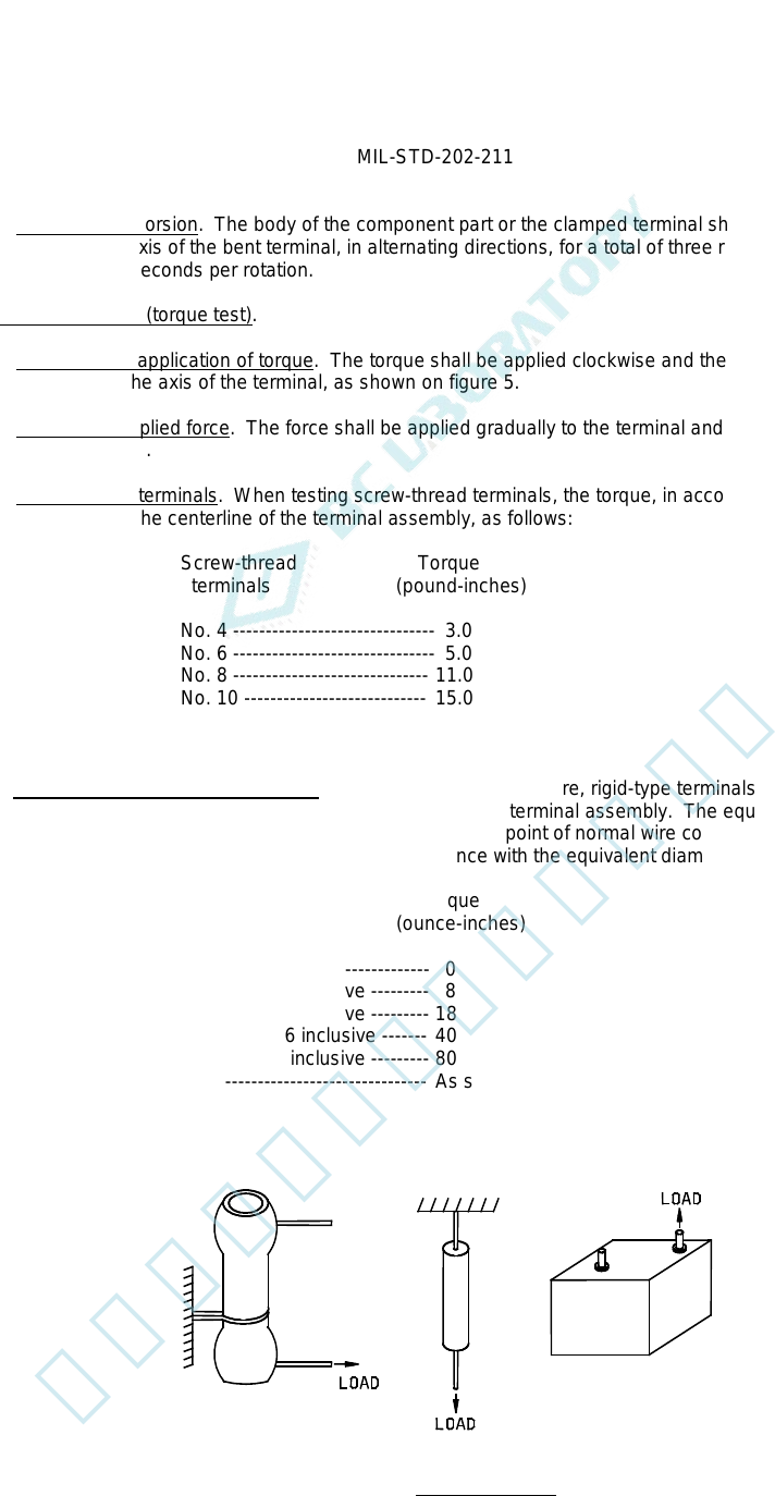
4.2.5.3 Screw-thread terminals. When testing screw-thread terminals, the torque, in accordance with the terminal
size, shall be applied to the centerline of the terminal assembly, as follows:
Screw-thread Torque
terminals (pound-inches)
No. 4 ------------------------------- 3.0
No. 6 ------------------------------- 5.0
No. 8 ------------------------------ 11.0
No. 10 ---------------------------- 15.0
No. 12 ---------------------------- 24.0
1/4 inch -------------------------- 32.0
4.2.5.4 Other non-wire, rigid-type terminals. When testing other non-wire, rigid-type terminals, the applied torque is
dependent on the equivalent diameter of the external portion of the terminal assembly. The equivalent diameter is
defined as equal to twice the distance from the terminal axis to the point of normal wire connection, as shown in the
examples on figure 6. The torque shall be applied in accordance with the equivalent diameter, as follows:
Equivalent diameter Torque
(inch) (ounce-inches)
1/16 or less --------------------- 0
>1/16 to 1/8 inclusive --------- 8
>1/8 to 3/16 inclusive --------- 18
>3/16 to 5/16 inclusive ------- 40
>5/16 to 1/2 inclusive --------- 80
>1/2 ------------------------------- As specified in the individual specification
FIGURE 1. Test condition A.
3
北测(上海)电子科技有限公司
联系方式:xuyj@beice-sh.com 13917165676