MIL-STD-202H.pdf - 第92页
MI L - S TD - 202 - 112 4.5 .2.2 Filte r . A filter s ha l l be us ed w hi c h i s c apa bl e of r e m o v i ng par t i c l es gr eat er t h an 1 m icron in size fr om the fluid. 4.5 .2.3 M agnifier . A 3 X m i ni m um m…
MIL-STD-202-112
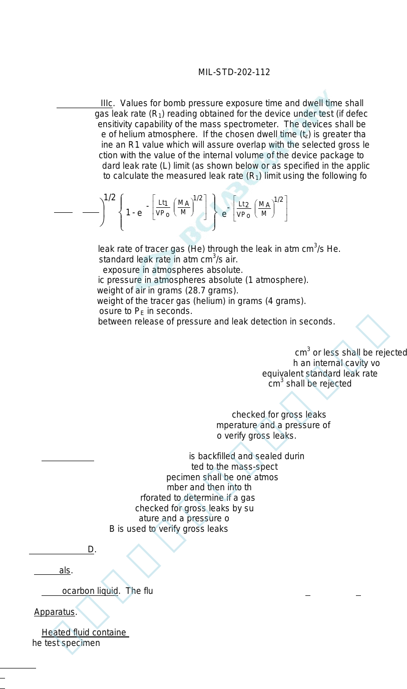
4.4.4.3.2.3 Procedure IIIc. Values for bomb pressure exposure time and dwell time shall be chosen such that
actual measured tracer gas leak rate (R
1
) reading obtained for the device under test (if defective) will be greater than
the minimum detection sensitivity capability of the mass spectrometer. The devices shall be subjected to a minimum
of 2 atmospheres absolute of helium atmosphere. If the chosen dwell time (t
z
) is greater than 60 minutes, graphs
shall be plotted to determine an R1 value which will assure overlap with the selected gross leak test condition. The
chosen values, in conjunction with the value of the internal volume of the device package to be tested and the
maximum equivalent standard leak rate (L) limit (as shown below or as specified in the applicable procurement
document), shall be used to calculate the measured leak rate (R
1
) limit using the following formula:
e
-
e
-
- 1
M
M
A
1/2
P
LP
=
R
M
M
A
1/2
VP
o
Lt
2
M
M
A
1/2
VP
o
Lt
1
O
E
1
R
1
= The measured leak rate of tracer gas (He) through the leak in atm cm
3
/s He.
L = The equivalent standard leak rate in atm cm
3
/s air.
P
E
= The pressure of exposure in atmospheres absolute.
P
O
= The atmospheric pressure in atmospheres absolute (1 atmosphere).
M
A
= The molecular weight of air in grams (28.7 grams).
M = The molecular weight of the tracer gas (helium) in grams (4 grams).
t
1
= The time of exposure to P
E
in seconds.
t
2
= The dwell time between release of pressure and leak detection in seconds.
V = The internal volume of the device package cavity in cubic centimeters.
Unless otherwise specified, devices with an internal cavity volume of 0.01 cm
3
or less shall be rejected if the
equivalent standard leak rate (L) exceeds 5 x 10
-8
atm cm
3
/s. Devices with an internal cavity volume greater than
0.01 cm
3
and equal to or less than 0.4 cm
3
shall be rejected if the equivalent standard leak rate (L) exceeds 1 x 10
-7
atm cm
3
/s. Devices with an internal cavity volume greater than 0.4 cm
3
shall be rejected if the equivalent standard
leak rate (L) exceeds 1 x 10
-6
atm cm
3
/s.
Upon completion of this procedure, the specimen shall be checked for gross leaks by subjecting the specimen either
to test condition A, B, or D. Water, at room ambient temperature and a pressure of 2.5 inches of mercury, may be
used in place of silicone oil, if test condition B is used to verify gross leaks.
4.4.4.4 Procedure IV. The specimen, which is backfilled and sealed during production with a known percentage of
tracer gas, shall be placed in a chamber connected to the mass-spectrometer-type leak detector, and the chamber
evacuated. The internal pressure of the specimen shall be one atmosphere or greater. If a leak exists, the gas
passes through the specimen into the chamber and then into the leak detector which will read the leakage rate. If
specified, the specimen shall be perforated to determine if a gas is actually present. Upon completion of this
procedure, the specimen shall be checked for gross leaks by subjecting the specimen either to test condition A, B, or
D. Water, at room ambient temperature and a pressure of 2.5 inches (63.5 mm) of mercury, may be used in place of
silicone oil, if test condition B is used to verify gross leaks.
4.5. Test condition D.
4.5.1 Materials.
4.5.1.1 Fluorocarbon liquid. The fluid shall be D02, D02-TS, D03, FC-40 1/ or FC-43 2/.
4.5.2 Apparatus.
4.5.2.1 Heated fluid container. The container for the fluid shall be made of pyrex glass and shall be sufficient size
to hold the test specimen in the fluid and to maintain a temperature of 125°C ±5°C (257°F ±9°F).
1/ D02, D02-TS, and D03 are the registered trade mark of Ausimont (Division of Montedison).
2/ Minnesota Mining Co. (3M) registered trade name.
9
北测(上海)电子科技有限公司
联系方式:xuyj@beice-sh.com 13917165676
MIL-STD-202-112
4.5.2.2 Filter. A filter shall be used which is capable of removing particles greater than 1 micron in size from the
fluid.
4.5.2.3 Magnifier. A 3X minimum magnifier or a stereo zoom microscope shall be used for observation of bubbles
emanating from the test specimens when immersed in the indicator fluid.
4.5.3 Precautions. The following precautions shall be observed:
a. Fluorocarbon liquids shall be filtered as specified in 4.5.2.2. Bulk filtering and storage is permissible. Leak
indicator fluids, which have accumulated observable quantities of particulate matter during use, shall be
discarded or reclaimed by filtration for reuse. Leak detecting fluids shall not be used for more than one
eight-hour shift without being refiltered.
b. The observation container shall contain sufficient fluid to assure coverage of the test specimen to a
minimum depth of two inches.
c. Illumination shall be a lighting source capable of providing at least 15,000 foot candles at the test specimen
position. The lighting source shall not require calibration but the light level shall be verified at the test
specimen position. The background behind the glass observation container should be a dull, non-reflective
black material.
d. The observation container should be covered at all times when not in use to minimize evaporation losses
and moisture adsorption.
e. Test specimens to be tested should be free from foreign material on the surface, including conformal
coatings and markings which may contribute to erroneous test results.
4.5.4 Procedure. The test specimens, mounted on specified fixtures to hold them in the fluid, shall be immersed,
with the uppermost portion at the minimum depth of 2 inches below the surface of the fluid, lid downward, one at a
time (or in such a configuration that a single bubble from a single specimen out of a group under observation may be
clearly observed as to its occurrence and source). The fluid shall be maintained at a temperature of 125°C ±5°C
(257°F ±9°F). The specimens shall be observed against a dull non-reflective black background through the magnifier
(see 4.5.2.3) from the instant of immersion until 20 seconds after immersion. Leakers will be identified by a single
bubble or a stream of bubbles. Specimens from which a single bubble is observed is considered to be a reject.
4.6. Test condition E.
4.6.1 Materials.
4.6.1.1 Fluorocarbon liquid. The fluids shall be D/80, FC-72 or PP-1 fluorocarbon detector fluids, and D02,
D02-TS, D03, FC-40, FC-43, PP-7 or PP-9 fluorocarbon indicator fluids.
4.6.2 Apparatus.
4.6.2.1 Heated fluid container. The container for the fluid shall be made of pyrex glass and shall be of sufficient
size to hold the test specimen in the fluid and to maintain a temperature of 125°C ±5°C (257°F ±9°F).
4.6.2.2 Filter. A filter shall be used which is capable of removing particles greater than 1 micron in size from the
fluid.
4.6.2.3 Magnifier. A magnifier with a magnification in the range between 3X to 30X for observation of bubbles
emanating from devices when immersed in the indicator fluid.
4.6.2.4 Chamber. A vacuum/pressure chamber for the evacuation and subsequent pressure bombing of device up
to 75 lbf/in
2
up to 10 hours.
10
北测(上海)电子科技有限公司
联系方式:xuyj@beice-sh.com 13917165676
MIL-STD-202-112
4.6.2.5 Lighting source. A lighting source capable of producing at least 15,000 foot candles in air at a distance
equal to that which the most distant device in the bath will be from the source.
4.6.2.6 Instruments. Suitable calibrated instruments to indicate the test temperature pressures and times are as
specified.
4.6.2.7 Fixtures. Suitable fixtures to hold the device(s) in the indicator fluid.
4.6.3 Precautions. The following precautions shall be observed.
a. Fluorocarbon liquids shall be filtered as specified in 4.6.2.2. Bulk filtering and storage is permissible. Leak
indicator fluids, which have accumulated observable quantities of particulate matter during use, shall be
discarded or reclaimed by filtration for reuse. Leak detecting fluids shall not be used for more than one
eight-hour shift without being refiltered.
b. The observation container shall contain sufficient fluid to assure coverage of the test specimen to a
minimum depth of two inches (50.8 mm).
c. Illumination shall be a lighting source capable of providing at least 15,000 foot candles at the test specimen
position. The lighting source shall not require calibration but the light level shall be verified at the test
specimen position. The background behind the glass observation container should be a dull, non-reflective
black material.
d. The observation container should be covered at all times when not in use to minimize evaporation losses
and moisture adsorption.
e. Test specimens to be tested should be free from foreign material on the surface, including conformal
coatings and markings that may contribute to erroneous test results.
f. Precautions should be taken to prevent operator injury due to package rupture or violent evolution of bomb
fluid when testing large packages.
4.6.4 Procedure. The test specimens mounted on specified fixtures to hold them in the leak detecting fluid shall be
inserted into the combination vacuum-pressure vessel and the applied ambient pressure shall be reduced to less
than 5 torr for 1 hour. Then without breaking vacuum, a sufficient quantity of leak detecting fluid (see 4.6.1.1) to
cover the test specimens, shall be drawn into the vacuum/pressure vessel by inserting a transfer tube from the
vacuum/pressure vessel into a container of leak detecting fluid and opening a valve in the tube. For test specimens
with an internal cavity volume of 0.1 cm
3
or less, the pressure in the vessel shall be increased to 90 lbf/in
2
and
maintained at that pressure for 3 hours minimum. For test specimens with an internal volume in excess of 0.1 cm
3
,
the pressure shall be increased to 50 lbf/in
2
and maintained at that pressure for 3 hours minimum. After
pressurization, the pressure shall be released from the pressure vessel and the test specimens shall be removed
from the pressure vessel, and retained in a bath containing the leak detecting fluid. Then they shall be dried for 3 ±1
minutes in air prior to immersion in the indicator fluid. The test specimens shall be immersed with the uppermost
portion at a minimum depth of 2 inches (50.8 mm) below the surface of the indicator fluid, lid downward, one at a time
(or in such a configuration that a single bubble from a single specimen out of a group under observation may be
clearly observed as to its occurrence and source. The leak indicator fluid shall be maintained at a temperature of
125°C ±5°C (257°F ±9°F). The test specimens shall be observed against a dull non-reflective black background
through the magnifier (see 4.6.2.3) from the instant of immersion until 20 seconds after immersion. Leaks will be
identified by a single bubble or a stream of bubbles. Specimens from which a single bubble is observed is
considered to be a reject.
4.7. Test condition F.
4.7.1 Materials.
4.7.1.1 Fluorocarbon liquid. The fluid used shall be FC-84 or D/80 fluorocarbon detector fluid.
11
北测(上海)电子科技有限公司
联系方式:xuyj@beice-sh.com 13917165676