MIL-STD-202H.pdf - 第87页
MI L - S TD - 202 - 112 4.4 .2.1 Mas s - spectro m et er - t y pe l e ak det e c t or . Fo r p r o c e d u r e s I, II, II Ia , I IIc , a n d IV o f th i s tes t condition, a commercia lly availabl e m a s s - s pec t r …
MIL-STD-202-112
4.3 Test condition B.
4.3.1 Materials.
4.3.1.1 Silicone oil. The oil used for the bath shall be clear silicone oil having a viscosity of 20 centistokes at 25°C
(77°F).
4.3.2 Apparatus.
4.3.2.1 Reduced pressure vessel. The vessel for the oil bath shall be of sufficient depth to immerse the uppermost
portion of the enclosure or seal to be tested to a depth of 1 inch (25.4 mm) below the surface of the bath, over which
can be drawn a vacuum resulting in an absolute pressure of not greater than 1.5 inches of mercury (not greater than
38.1 torr).
4.3.2.2 Vacuum pump. The vacuum pump shall be capable of evacuating and holding a vacuum resulting in an
absolute pressure of not greater than 1.5 inches of mercury (not greater than 38.1 torr) for a minimum duration of 1
minute in the reduced pressure vessel (see 4.3.2.1).
4.3.2.3 Degassing of silicone oil. The silicone oil shall be placed in the test fixture and a pressure of 1 inch (25.4
mm) of mercury or less attained over the fluid for as long as is necessary to degas the fluid. Such degassing is
complete when no further bubbling or frothing is present in the fluid. Throughout the test, components shall be
lowered gently in the fluid to prevent aeration of the fluid. The fluid shall not be poured from one container to another
without first being degassed again before testing.
4.3.3 Preparation of specimens. As specified in 4.2.4.
4.3.4 Procedure. This test consists of one immersion of the specimen or group of specimens into a bath of clear
silicone oil (see 4.3.1.1) maintained at room ambient temperature. The specimen shall be placed in the oil bath with
the critical side (or side of special interest) in a horizontal position facing up. If the specimen has no critical side, it
shall be placed in the bath with its major axis in a horizontal position. The specimen shall be completely submerged
in the bath with the uppermost portion of the enclosure or seal at a depth of 1 inch (25.4 mm). A vacuum resulting in
an absolute pressure of not greater than 1.5 inches of mercury (not greater than 38.1 torr) shall be drawn and held
over the bath for a minimum duration of 1 minute. The specimen shall be carefully observed during the entire
duration of the immersion for indication of a poor seal as evidenced by a continuous stream of bubbles emanating
from the specimen. After the test is completed, the specimen shall be cleaned in a suitable degreaser and permitted
to dry thoroughly before any additional tests are performed.
4.3.5 Precaution. This test condition should not be used either as a separate test or a gross leak test for
component parts which are to be subsequently attached to printed circuit board assemblies. Since complete removal
of silicone oil residues is difficult, the oil will be transferred unknowingly to other parts during assembly processes.
Traces of silicone can result in poor solder wettability of component part leads, poor adhesion to sealants, and
mealing of the conformal coating on the printed circuit board.
4.4 Test condition C.
4.4.1 Materials.
4.4.1.1 Tracer gases. When performing tests in accordance with procedures I, II, and IV of this condition, tracer
gases, i.e., helium, argon, or other rare gas, or a mixture of a gas with nitrogen (such as 90 percent nitrogen and 10
percent helium) shall be used. The tracer gas used in procedures IIIa and IIIc shall be helium. The tracer gas used
in procedure IIIb shall be the radioactive gas, krypton 85.
4.4.2 Apparatus. For all the procedures of this test condition, the test apparatus, exclusive of pressurization
equipment, shall be calibrated using a diffusion type calibrated standard leak at least once each working shift.
4
北测(上海)电子科技有限公司
联系方式:xuyj@beice-sh.com 13917165676
MIL-STD-202-112
4.4.2.1 Mass-spectrometer-type leak detector. For procedures I, II, IIIa, IIIc, and IV of this test condition, a
commercially available mass-spectrometer-type leak detector, preset to read a tracer-gas content, shall be used to
measure the leakage rate of gas through a faulty seal. Another instrument may be used if it can be demonstrated to
the Government that the instrument, properly calibrated to read tracer-gas content, has the required
leakage-detection sensitivity (see 4.1.1).
4.4.2.1.1 Chambers. Depending on which procedure is used (see 4.4.4), suitable pressure or vacuum chambers
are required.
4.4.2.1.2 Pumps. Depending on which procedure is used (see 4.4.4), suitable pressure or vacuum pumps are
required.
4.4.2.2 Radioactive-gas detection apparatus. Apparatus for procedure IIIb shall consist of:
a. Radioactive tracer gas activation console.
b. Counting equipment consisting of a scintillation crystal, photomultiplier tube, preamplifier, ratemeter, and
krypton 85 reference standards. The counting station shall be of sufficient sensitivity to determine through
the device wall the radiation level of any krypton 85 tracer gas present within the device. The counting
station shall have a minimum sensitivity, in c/m per µCi, corresponding to a leak rate of 10
-9
atm cm
3
/ s of
krypton 85 and shall be calibrated at least once every working shift using krypton 85 reference standards
and following the equipment manufacturer's instruction.
c. A tracer gas consisting of a mixture of krypton 85 and dry nitrogen. The concentration of krypton 85 in dry
nitrogen shall be no less than 100 microcuries per atmospheric cubic centimeter. This value shall be
determined at least once each 30 days and recorded in accordance with the calibration requirements of this
standard.
4.4.3 Supplementary tests. When parts to be tested are normally evacuated through a tube and are sealed in
some manner prior to delivery, procedures I and II (see 4.4.4.1 and 4.4.4.2) will require a separate verification of the
seal of the evacuation tube in conjunction with this test method, using the mass-spectrometer-type leak detector (see
4.4.2.1). The verification may be accomplished by backfilling the specimen with air or gas at a specified pressure and
then submitting the specimen to either procedure IIIa, IIIb, IIIc, or IV.
4.4.4 Procedures. This test condition consists of five procedures (see 4.4.4.1 to 4.4.4.4, inclusive), the choice of
which must be specified in the individual specification. Procedure IV is the preferred method of performing this test
for parts that are not evacuated.
4.4.4.1 Procedure I. The mass-spectrometer-type leak detector shall be coupled to the unsealed evacuation tube
of the specimen, and a vacuum created within the specimen. It is extremely important that the coupling connections
between the specimen and the leak detector be perfectly sealed. The specimen shall then be subjected to a gas
atmosphere either by surrounding the specimen with the gas or by spraying the specimen thoroughly with a jet of the
gas. If a defect exists in the specimen, an amount of gas that depends upon the size of the defect will be drawn
through it and passed into the leak detector, which will read the leakage rate. When this portion of the procedure is
completed, the specimen shall be filled with air or gas at a specified pressure and having a known percentage of
tracer gas. The evacuation tube shall then be pinched off and sealed. After sealing, the seal of the tube shall be
verified by either procedure IIIa, IIIb, IIIc or IV, if filled with tracer gas.
5
北测(上海)电子科技有限公司
联系方式:xuyj@beice-sh.com 13917165676
MIL-STD-202-112
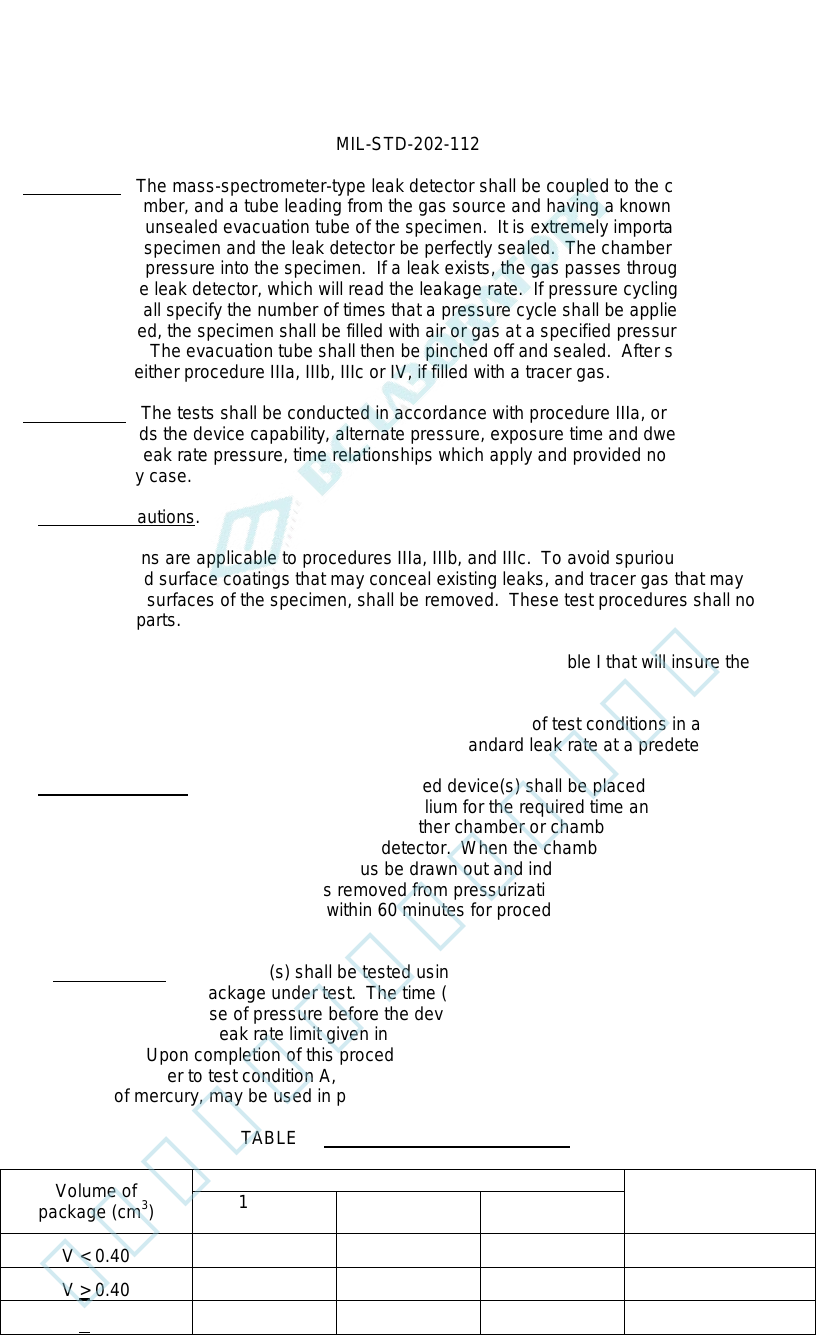
4.4.4.2 Procedure II. The mass-spectrometer-type leak detector shall be coupled to the chamber. The specimen
shall be placed in the chamber, and a tube leading from the gas source and having a known percentage of tracer gas
shall be connected to the unsealed evacuation tube of the specimen. It is extremely important that the coupling
connections between the specimen and the leak detector be perfectly sealed. The chamber shall then be evacuated
and the gas forced under pressure into the specimen. If a leak exists, the gas passes through the specimen into the
chamber and then into the leak detector, which will read the leakage rate. If pressure cycling is required, the
individual specification shall specify the number of times that a pressure cycle shall be applied. When this portion of
the procedure is completed, the specimen shall be filled with air or gas at a specified pressure and having a known
percentage of tracer gas. The evacuation tube shall then be pinched off and sealed. After sealing, the seal of the
tube shall be verified by either procedure IIIa, IIIb, IIIc or IV, if filled with a tracer gas.
4.4.4.3 Procedure III. The tests shall be conducted in accordance with procedure IIIa, or IIIc. When bomb
pressure specified exceeds the device capability, alternate pressure, exposure time and dwell time may be used
provided they satisfy the leak rate pressure, time relationships which apply and provided no less than 30 psig bomb
pressure is applied in any case.
4.4.4.3.1 Testing precautions.
a. These precautions are applicable to procedures IIIa, IIIb, and IIIc. To avoid spurious indications,
contaminants and surface coatings that may conceal existing leaks, and tracer gas that may be absorbed or
adsorbed on the surfaces of the specimen, shall be removed. These test procedures shall not apply to
organic-coated parts.
b. Test procedure IIIa is a "fixed" method with specified conditions per table I that will insure the test sensitivity
necessary to detect the required leak rate (R1).
c. Test procedure IIIc is a "flexible" method that allows the variance of test conditions in accordance with the
formula of 4.4.4.3.2.3 to detect the specified equivalent standard leak rate at a predetermined leak rate (R1).
4.4.4.3.2 General procedure. For IIIa and IIIc the completed device(s) shall be placed in a sealed chamber which
is then pressurized with a tracer gas of 100 +0, -5 percent helium for the required time and pressure. The pressure
shall then be relieved and each specimen transferred to another chamber or chambers which are connected to the
evacuating system and a mass-spectrometer-type leak detector. When the chamber(s) is evacuated, any tracer gas
which was previously forced into the specimen will thus be drawn out and indicated by the leak detector as a
measured leak rate (R1). The number of devices removed from pressurization for leak testing shall be limited such
that the test of the last device can be completed within 60 minutes for procedure IIIa or within the chosen value of
dwell time (t
z
) for procedure IIIc.
4.4.4.3.2.1 Procedure IIIa. The device(s) shall be tested using the appropriate conditions specified in table I for
the internal cavity volume of the package under test. The time (t) is the time under pressure and time (t
z
) is the
maximum time allowed after release of pressure before the device(s) shall be read. This method shall not be used if
the maximum equivalent standard leak rate limit given in the procurement document is less than the limits specified
herein for procedure IIIc. Upon completion of this procedure, the specimen shall be checked for gross leaks by
subjecting the specimen either to test condition A, B, or D. Water, at room ambient temperature and a pressure of
2.5 inches (63.5 mm) of mercury, may be used in place of silicone oil, if test condition B is used to verify gross leaks.
TABLE I. Fixed conditions procedure IIIa.
Volume of
package (cm
3
)
Bomb condition R1
Reject limit
(atm cm
3
/s He)
1bf/in
2
gage
Exposure time
hours
Maximum
dwell hours
V < 0.40 60 ±2 2 +0.2, -0 1 5 x 10
-8
V > 0.40 60 ±2 2 +0.2, -0 1 2 x 10
-7
V > 0.40 30 ±2 4 +0.4, -0 1 1 x 10
-7
6
北测(上海)电子科技有限公司
联系方式:xuyj@beice-sh.com 13917165676