MIL-STD-202H.pdf - 第196页
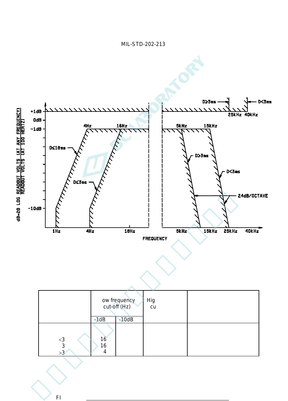
MI L - S TD - 202 -2 1 3 Duration of pulse (ms) L ow f r equen c y c ut - o ff ( H z ) H i g h freque ncy c u t - off (k Hz) - 1 dB Frequency bey ond which the response may rise above +1 dB (kHz) - 1dB - 10dB 3 < 3 3 …
MIL-STD-202-213
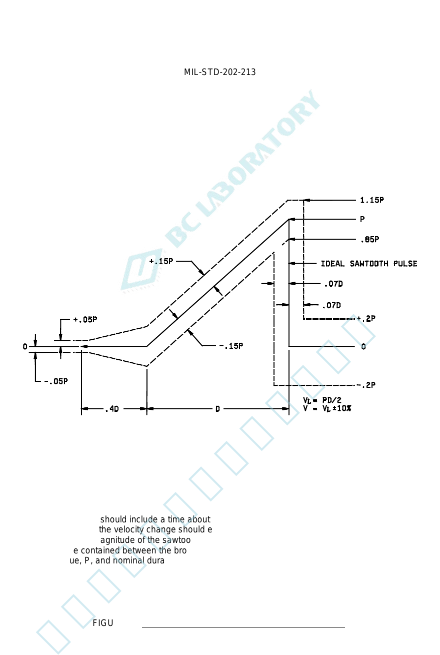
NOTE: The oscillogram should include a time about 3D long with the pulse approximately in the center. The
integration to determine the velocity change should extend from .4D before the pulse to .1D beyond the pulse.
The peak acceleration magnitude of the sawtooth pulse is P and its duration is D. Any measured acceleration
pulse which can be contained between the broken line boundaries is a nominal terminal-peak sawtooth pulse of
nominal peak value, P, and nominal duration, D. The velocity change associated with the measured acceleration
pulse is V.
FIGURE 2. Tolerances for terminal-peak sawtooth shock pulse.
3
北测(上海)电子科技有限公司
联系方式:xuyj@beice-sh.com 13917165676
MIL-STD-202-213
Duration of pulse
(ms)
Low frequency
cut-off (Hz)
High frequency
cut-off (kHz)
-1 dB
Frequency beyond which
the response may rise
above +1 dB (kHz)
-1dB -10dB
3
<3
3
>3
16
16
4
4
4
1
15
5
5
40
25
25
FIGURE 3. Tolerance limits for measuring system frequency response.
4
北测(上海)电子科技有限公司
联系方式:xuyj@beice-sh.com 13917165676
MIL-STD-202-213
4.1.2.2 Transducer. The fundamental resonant frequency of the accelerometer shall be greater than 30,000 Hz,
when the accelerator is employed as the shock sensor.
4.1.2.3 Transducer calibration. Transducers shall be calibrated in accordance with ASA STD S2.2
. The accuracy
of the calibration method shall be at least ±5 percent over the frequency range of 2 to 5,000 Hz. The amplitude of the
transducer being calibrated shall also be ±5 percent over the frequency range of 4 to 5,000 Hz.
4.1.2.4 Linearity. The signal level of the system shall be chosen so that the acceleration pulse operates over the
linear portion of the system.
4.1.2.5 Transducer mounting. When conformance to 4.1.3 is required, the monitoring transducer shall be rigidly
secured and located as near as possible to an attachment point of the specimen but not on the specimen itself.
4.1.3 Application of shock measuring instrumentation. Shock measuring instrumentation shall be utilized to
determine that the correct input shock pulse is applied to the test specimen. This is particularly important where a
multi-specimen test is made. Generally, the shock pulse should be monitored whenever there is a change in the test
setup, such as a different test fixture, different component (change in physical characteristics), different weight,
different shock pulse (change in pulse shape, intensity, or duration) or different shock machine characteristics. It is
not mandatory that each individual shock be monitored, provided that the repeatability of the shock application as
specified in 4.1.1.1 has been established.
4.2 Shock pulses. Two types of shock pulses, a half-sine shock pulse and a sawtooth shock pulse, are specified.
The pulse shape and tolerances are shown on figures 1 and 2, respectively. For single degree of freedom systems, a
sawtooth shock pulse can be assumed to have a damage potential at least as great as that of the half-sine pulse if
the shock spectrum of the sawtooth pulse is everywhere at least as great as that of the half-sine pulse. This
condition will exist for two such pulses of the same duration if over most of the spectrum the acceleration peak value
of the sawtooth pulse is 1.4 times the acceleration peak value of the half-sine pulse.
4.2.1 Half-sine shock pulse. The half-sine shock pulse shall be as indicated on figure 1. The velocity change of
the pulse shall be within ±10 percent of the velocity change of the desired shock pulse. The velocity change may be
determined either by direct measurement, indirectly, or by integrating (graphically or electrically) the area (faired
acceleration pulse may be used for the graphical representation) under the measured acceleration pulse. For half-
sine acceleration pulses of less than 3 milliseconds duration the following tolerances should apply: The faired
maximum value of the measured pulse shall be within ±20 percent of the specified ideal pulse amplitude, its duration
shall be within ±15 percent of the specified ideal pulse duration, and the velocity change associated with the
measured pulse shall be within ±10 percent of V
i
= 2AD/π. See figure 1. The measured pulse will then be considered
a nominal half-sine pulse with a nominal amplitude and duration equal to respective values of the corresponding ideal
half-sine pulse. The duration of the measured pulse shall be taken as D
m
= D(.1A)/.94; where D(.1A) is the time
between points at .1A for the faired measured acceleration pulse.
4.2.1.1 The ideal half-sine pulse. An ideal half-sine acceleration pulse is given by the solid curve. See figure 1.
The measured acceleration pulse must lie within the boundaries given by the broken lines. In addition, the actual
velocity change of the shock must be within 10 percent of the ideal velocity change. The actual velocity change can
be determined by direct measurements, or from the area under the measured acceleration curve. The ideal velocity
change is equal to V
i
= 2AD/π; where A is the acceleration amplitude and D is the pulse duration of the ideal pulse.
4.2.2 Sawtooth shock pulse. The sawtooth pulse shall be as indicated on figure 2. The velocity change of the
faired measured pulse shall be within ±10 percent of the velocity change of the ideal pulse.
4.2.2.1 The ideal terminal-peak sawtooth. An ideal terminal-peak sawtooth acceleration pulse is given by the solid
line. See figure 2. The measured acceleration pulse must be within the boundaries given by the broken lines. In
addition, the actual velocity change of the shock pulse must be within 10 percent of the ideal value. The actual
velocity change can be determined from direct measurements, or from the area under the measured acceleration
curve. The ideal velocity change is equal to V
i
= PD/2; where P is the peak value of acceleration, and D is the pulse
duration.
5
北测(上海)电子科技有限公司
联系方式:xuyj@beice-sh.com 13917165676