MIL-STD-202H.pdf - 第155页
MI L - S TD - 202 - 20 8 5. DETAILED REQUI RE M E N T S 5. 1 Summary . The f oll ow i ng det ai l s ar e t o be s p ec i f i ed i n t h e i nd i v i dua l s pec i f i c at i on: a. Depth of immers i o n i f ot h er t h a…
MIL-STD-202-208
4.5. Soldering iron test method. When specified in the individual specification, the soldering iron test
method shall be performed as specified herein.
4.5.1 Apparatus. The soldering iron used shall be temperature controlled and shall be capable of maintaining the
measured idling tip temperature within ±5.5°C. Three-wire cords and tip grounding shall be used. The solder iron
shall be of such design as to provide zero voltage switching. Solder guns of the transformer type shall not be used.
4.5.2 Materials. The solder shall be composition Sn60Pb40A or Sn63Pb37A of J-STD-006
“Requirements for
Electronic Grade Solder Alloys and Fluxed and Non-Fluxed Solid Solders for Electronic Soldering Applications”. The
solder shall be of form W, flux symbol A, flux percentage symbol 6 or 7 (see
J-STD-006).
4.5.3 Procedure. Preparation of terminations and aging shall be as specified in J-STD-002
and 4.4 above. Flux
shall be applied by a suitable method (e.g., brush) and allowed to drain for 5 to 20 seconds. Solder in accordance
with 4.5.2 shall be applied to the terminal along with the clean solder coated tip of an iron (unless otherwise specified
in the individual specification, iron temperature shall be 350°C) to a point ¼ inch from the nearest insulating material
or ½ the exposed length of the terminal, whichever is closer. The termination shall be positioned so that the iron can
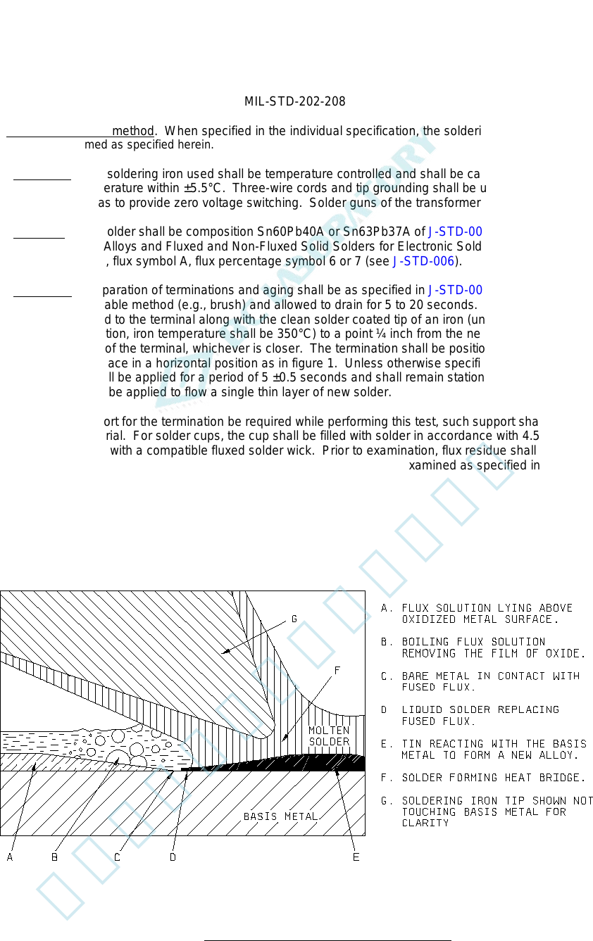
be applied to the test surface in a horizontal position as in figure 1. Unless otherwise specified in the individual
specification, the iron shall be applied for a period of 5 ±0.5 seconds and shall remain stationary during this period.
Only enough solder shall be applied to flow a single thin layer of new solder.
Should mechanical support for the termination be required while performing this test, such support shall be of
thermally insulating material. For solder cups, the cup shall be filled with solder in accordance with 4.5.2, and the
excess solder wicked out with a compatible fluxed solder wick. Prior to examination, flux residue shall be removed
from the terminations by cleaning in a suitable solvent. Terminations shall be examined as specified in
ANSI/J-STD-002.
FIGURE 1. Soldering iron position and process diagram.
2
北测(上海)电子科技有限公司
联系方式:xuyj@beice-sh.com 13917165676
MIL-STD-202-208
5. DETAILED REQUIREMENTS
5.1 Summary. The following details are to be specified in the individual specification:
a. Depth of immersion if other than specified.
b. Angle of immersion for surface mount leaded components, if other than 90°.
c. Measurements after test, when applicable.
d. Whether soldering iron method is to be used.
1. Soldering iron temperature if other than 350°C.
2. Duration of application of soldering iron if other than 5 ±0.5 seconds.
6. NOTES
(This section contains information of a general or explanatory nature that may be helpful, but is not mandatory.)
6.1 Supersession data. The main body and 38 parts of this revision of MIL-STD-202 replace superseded MIL-STD-
202.
Custodians: Preparing activity:
Army - CR DLA – CC
Navy - EC
Air Force - 85 (Project 59GP-2015-022)
DLA - CC
Review activities:
Army - AR, AT, AV, CR4, MI, SM, TE
Navy - AS, OS, SH
Air Force - 19, 99
NSA - NS
NOTE: The activities listed above were interested in this document as of the date of this document. Since
organizations and responsibilities can change, you should verify the currency of the information above using the
ASSIST Online database at https://assist.dla.mil/
3
北测(上海)电子科技有限公司
联系方式:xuyj@beice-sh.com 13917165676
INCH-POUND
MIL-STD-202-209
18 April 2015
SUPERSEDING
MIL-STD-202G
w/CHANGE 2 (IN PART)
28 June 2013
(see 6.1)
DEPARTMENT OF DEFENSE
TEST METHOD STANDARD
METHOD 209, RADIOGRAPHIC INSPECTION
AMSC N/A FSC 59GP
北测(上海)电子科技有限公司
联系方式:xuyj@beice-sh.com 13917165676