MIL-STD-202H.pdf - 第225页
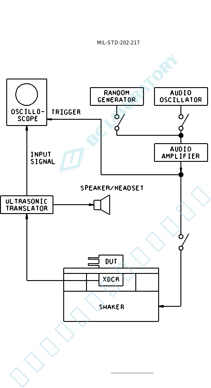
MI L - S TD - 202 - 217 FIGURE 1. Typical test circui t . 4 北测(上海)电子科技有限公 司 联系方式:xuyj@beice-sh.com 13917165676
MIL-STD-202-217
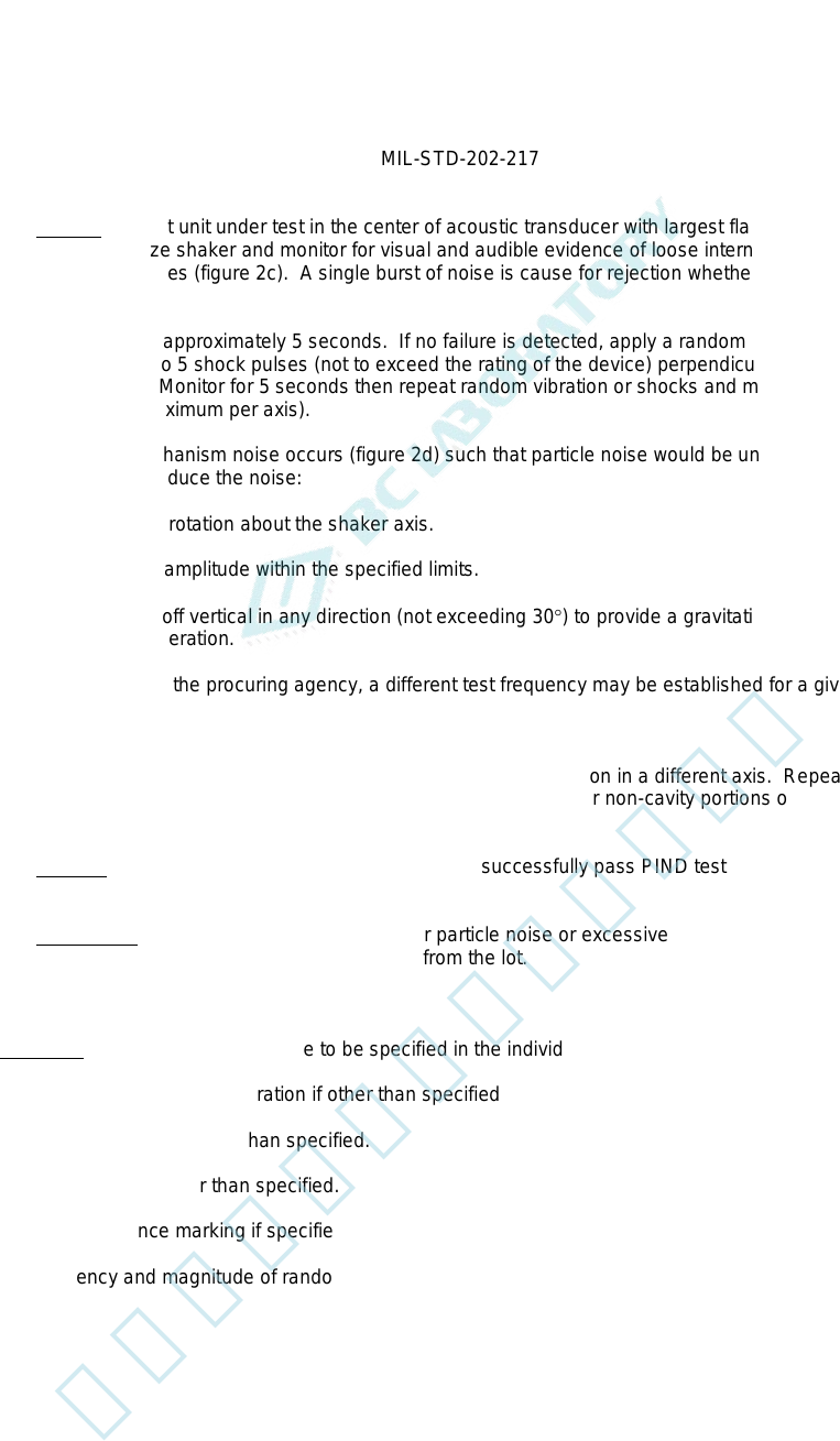
4.2.3.3 Testing. Mount unit under test in the center of acoustic transducer with largest flat surface down
(paragraph 4b). Energize shaker and monitor for visual and audible evidence of loose internal material as evidenced
by nonperiodic noise spikes (figure 2c). A single burst of noise is cause for rejection whether or not the indication can
be repeated.
Allow test to proceed for approximately 5 seconds. If no failure is detected, apply a random acceleration for 3
seconds maximum or 3 to 5 shock pulses (not to exceed the rating of the device) perpendicular to the axis of
vibration (see figure 3). Monitor for 5 seconds then repeat random vibration or shocks and monitor for an additional 5
seconds (30 seconds maximum per axis).
NOTE: If excessive mechanism noise occurs (figure 2d) such that particle noise would be undetectable, the following
action may be taken to reduce the noise:
a. Reorient unit by rotation about the shaker axis.
b. Change shaker amplitude within the specified limits.
c. Tilt shaker axis off vertical in any direction (not exceeding 30°) to provide a gravitational side component to
the shaker acceleration.
d. With approval of the procuring agency, a different test frequency may be established for a given device.
e. Cancel out periodic noise.
If no particle is detected rotate unit to another flat surface providing vibration in a different axis. Repeat above test for
not to exceed 30 seconds. Units shall not be tested with terminals or other non-cavity portions of the assembly in
contact with the transducer.
4.2.3.4 Marking. If specified (see 5.1d), those units which successfully pass PIND test shall be marked "PIND" on
any surface providing existing markings are not obscured.
4.2.3.5 Failed units. Those units which exhibit either particle noise or excessive mechanism noise which cannot
be eliminated as described in 4.2.3.3 shall be rejected from the lot.
5. DETAILED REQUIREMENTS
5.1 Summary. The following details are to be specified in the individual specification:
a. Test frequency and acceleration if other than specified.
b. Axes of vibration if other than specified.
c. Test duration if other than specified.
d. Test acceptance marking if specified.
e. Frequency and magnitude of random noise generator shall be specified.
3
北测(上海)电子科技有限公司
联系方式:xuyj@beice-sh.com 13917165676
MIL-STD-202-217
FIGURE 1. Typical test circuit.
4
北测(上海)电子科技有限公司
联系方式:xuyj@beice-sh.com 13917165676
MIL-STD-202-217
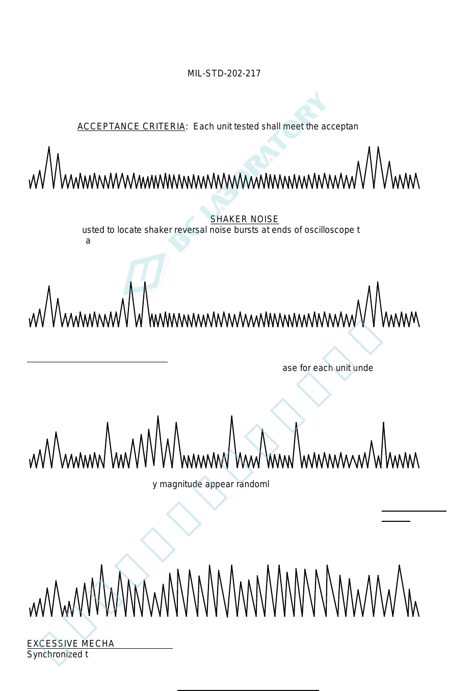
ACCEPTANCE CRITERIA: Each unit tested shall meet the acceptance.
SHAKER NOISE
Timebase adjusted to locate shaker reversal noise bursts at ends of oscilloscope trace. Test unit
not mounted. a
INHERENT MECHANICAL NOISE
Synchronized spike may appear at different locations on time base for each unit under test. b
Non-synchronized spikes of any magnitude appear randomly and may disappear as test progresses. Unit
is rejectable. c
EXCESSIVE MECHANICAL NOISE
Synchronized trace masks more than 50% of oscilloscope trace. Unit is rejectable. d
FIGURE 2. Representative oscilloscope traces.
PARTICULATE
NOISE
5
北测(上海)电子科技有限公司
联系方式:xuyj@beice-sh.com 13917165676