MIL-STD-202H.pdf - 第271页
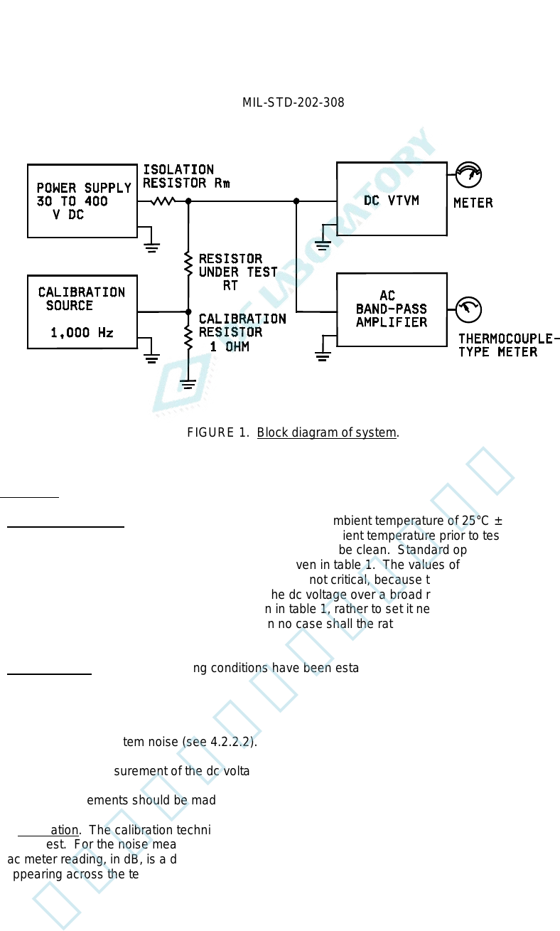
MI L - S TD - 202 - 308 F I G URE 1 . B l o c k di a gr am of s y s t em . 4.2. Procedure. 4.2.1 Oper ating condition s . The test s hall be perf ormed at a n a m bi en t t e m per at ur e of 2 5° C ± 2°C , unless otherw…
MIL-STD-202-308
3. DEFINTIONS
This section not applicable to this standard.
4. GENERAL REQUIREMENTS
4.1. Apparatus. Noise measurements should be made on Quan-Tech Laboratories, Inc., Model 315 Resistor-Noise Test
Set, or equal, built in conformance with specifications recommended by the National Bureau of Standards (NBS) and
detailed in a report entitled "A Recommended Standard Resistor-Noise Test System," by G.T. Conrad, Jr., N. Newman, and
A.P. Stansbury published in the IRE Transactions of the Professional Group on Component Parts, Volume CP-7, Number 3,
September 1960. The NBS-test system provides a means for establishing direct current through the resistor under test and
measuring the resulting dc voltage and noise voltage appearing at the terminals of the resistor. These two voltages are
indicated simultaneously on scales calibrated in db. Instrumentation is so arranged that the associated value of the
"microvolts-per-volt-in-a-decade" index may be readily determined in accordance with 4.2.3.
4.1.1 Test system. The test system shall be as shown in the simplified block diagram on figure 1. The dc portion
of the system consists of a variable dc power supply and a dc vacuum-tube voltmeter (VTVM). The alternating-
current (ac) portion of the system consists of a calibration signal source and an indicating amplifier. The
interconnecting leads, as well as the resistor under test, should be adequately shielded.
4.1.1.1 DC measurement considerations. The variable dc power supply furnishes dc loading power through an
isolation resistor to the resistor under test. The isolation resistor prevents noise, appearing at the terminals of the
resistor under test, from being severely attenuated by the very low, parallel impedance presented by the output
terminals of the dc power supply. The isolation resistor must be free of current noise. Quiet wirewound-type resistors
are suitable. One of four values for the isolation resistor, Rm, (1,000 ohms, 10,000 ohms, 100,000 ohms, or 1
megohm (mego)) is selected, depending on the resistance of the resistor under test, RT. The dc voltage appearing
across the resistor under test is indicated by the dc VTVM. The meter has two scales - one showing the dc voltage
across the resistor under test, V, and the other indicating the quantity D-20 log V, in dB. The scale simplifies
computation of the current-noise index. The choice of value of the dc voltage is not critical, however, to avoid
subjecting the resistor under test, and the isolation resistor as well, to excessive dc power dissipation or voltage, or
both, standard nominal values of dc voltage and values for the isolation resistor are given in table 1.
4.1.1.2 AC measurement considerations. Noise voltage appearing at the terminals of the resistor under test is
amplified and its rms magnitude is shown by the ac indicating amplifier. The indicating amplifier consists of a high-
gain, low-noise amplifier, a filter, an rms detector, and an output meter. The filter restricts the frequency response of
the amplifier to a flat-top, 1,000 Hz pass band, geometrically centered at 1,000 Hz. The output-meter scale, like that
of the dc VTVM, is calibrated in dB to simplify calculations.
4.1.1.3 Calibration technique. The calibration technique consists of first applying a predetermined value of 1,000
Hz, sine-wave signal across a 1 ohm resistor located in series with the resistor under test, and then adjusting the gain
of the amplifier, by means of a variable attenuator, until the output meter deflects to the "calibrate" line. This
procedure standardizes the gain of the system and calibrates the indicating amplifier. It should be noted that since
the calibration setting depends upon the impedance at 1,000 Hz of the resistor under test, resistors having the same
dc resistance may not calibrate alike. The resistance of the calibration resistor (1 ohm) is considered negligible
compared to that of any resistor under test (100 ohms to 22 mego); therefore, the effect of the calibration voltage
appearing at the terminals of a zero-impedance generator located in series with the resistor under test. The
magnitude of the calibration voltage is so chosen that the indicated output is equal to that which would be obtained if
the calibration voltage were a noise voltage having an rms value of 1,000 µv in a decade. Such a signal should
produce a reading of 60 dB when the system is properly calibrated; thus, 0 dB means 1 µv in a decade.
4.1.2 Synopsis. To summarize, this apparatus provides a measure of the rms value of the current-noise voltage
generated in the resistor under test and transmitted in a frequency decade. The calibration technique refers the
measured noise voltage to the terminals of an essentially zero-impedance noise-voltage generator located in series
with the resistor under test. The noise voltage so measured, when corrected for the presence of system noise, is the
"open circuit" current-noise voltage of the resistor under test. Since both the current-noise voltage and dc voltage are
expressed in dB, the value of the “microvolts-per-volt-in-a-decade" index is obtained by subtracting the dc reading
from the corrected noise reading. The corrected noise reading is discussed in 4.2.2.3.
2
北测(上海)电子科技有限公司
联系方式:xuyj@beice-sh.com 13917165676
MIL-STD-202-308
FIGURE 1. Block diagram of system.
4.2. Procedure.
4.2.1 Operating conditions. The test shall be performed at an ambient temperature of 25°C ±2°C, unless otherwise
specified. The specimen under test shall be stabilized at room ambient temperature prior to test. No special
preparations of the specimen are required other than that its leads be clean. Standard operating conditions, based
on the resistance value of the specimen to be tested, are given in table 1. The values of the isolation resistor, Rm,
and the dc voltage, V, should be observed, although they are not critical, because the index is reasonably
independent of the values of the isolation resistor and the dc voltage over a broad range. Therefore, it is not
necessary to obtain the exact value of dc voltage given in table 1, rather to set it near the value, and to read carefully
and record its value at the time of the measurement. In no case shall the ratings of the resistor under test be
exceeded.
4.2.2 Measurements. After the operating conditions have been established, the measurement operation shall be
performed in three steps, as follows:
(1) Calibration (see 4.2.2.1).
(2) Measurement of system noise (see 4.2.2.2).
(3) Simultaneous measurement of the dc voltage and the resulting total noise (see 4.2.2.3).
Generally, the measurements should be made in the order listed. The precautions in 1.2 should be observed.
4.2.2.1 Calibration. The calibration technique (see 4.1.1.3) standardizes the gain of the ac system for the particular
resistor under test. For the noise measurements in steps 2 and 3 which follow, the sum of the ac attenuator setting
and the ac meter reading, in dB, is a direct indication of the noise present in terms of an "open-circuit" rms noise
voltage appearing across the terminals of the resistor under test.
3
北测(上海)电子科技有限公司
联系方式:xuyj@beice-sh.com 13917165676
MIL-STD-202-308
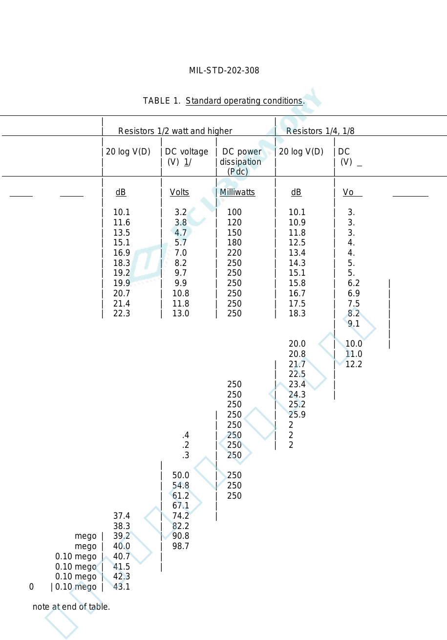
TABLE 1. Standard operating conditions.
| | | |
| Resistance | Resistors 1/2 watt and higher | Resistors 1/4, 1/8, and 1/10 watt |
| | | | | | | | |
| Resistor | Isolation | 20 log V(D) | DC voltage | DC power | 20 log V(D) | DC voltage | DC power |
| under | resistor | | (V) 1/ | dissipation | | (V) 1/ | dissipation |
| test (Rt) | (Rm) | | | (Pdc) | | | (Pdc) |
| | | | | | | | |
| Ohms | Ohms | dB | Volts | Milliwatts | dB | Volts | Milliwatts |
| | | | | | | | |
| 100 | 1,000 | 10.1 | 3.2 | 100 | 10.1 | 3.2 | 100 |
| 120 | 1,000 | 11.6 | 3.8 | 120 | 10.9 | 3.5 | 100 |
| 150 | 1,000 | 13.5 | 4.7 | 150 | 11.8 | 3.9 | 100 |
| 180 | 1,000 | 15.1 | 5.7 | 180 | 12.5 | 4.2 | 100 |
| 220 | 1,000 | 16.9 | 7.0 | 220 | 13.4 | 4.7 | 100 |
| 270 | 1,000 | 18.3 | 8.2 | 250 | 14.3 | 5.2 | 100 |
| 330 | 1,000 | 19.2 | 9.7 | 250 | 15.1 | 5.7 | 100 |
| 390 | 1,000 | 19.9 | 9.9 | 250 | 15.8 | 6.2 | 100 |
| 470 | 1,000 | 20.7 | 10.8 | 250 | 16.7 | 6.9 | 100 |
| 560 | 1,000 | 21.4 | 11.8 | 250 | 17.5 | 7.5 | 100 |
| 680 | 1,000 | 22.3 | 13.0 | 250 | 18.3 | 8.2 | 100 |
| 820 | 1,000 | 23.1 | 14.3 | 250 | 19.2 | 9.1 | 100 |
| | | | | | | | |
| 1,000 | 1,000 | 24.0 | 15.8 | 250 | 20.0 | 10.0 | 100 |
| 1,200 | 1,000 | 24.8 | 17.3 | 250 | 20.8 | 11.0 | 100 |
| 1,500 | 1,000 | 25.8 | 19.4 | 250 | 21.7 | 12.2 | 100 |
| 1,800 | 1,000 | 26.6 | 21.2 | 250 | 22.5 | 13.4 | 100 |
| 2,200 | 1,000 | 27.4 | 23.4 | 250 | 23.4 | 14.8 | 100 |
| 2,700 | 10,000 | 28.3 | 26.0 | 250 | 24.3 | 16.4 | 100 |
| 3,300 | 10,000 | 29.2 | 28.7 | 250 | 25.2 | 18.2 | 100 |
| 3,900 | 10,000 | 29.9 | 31.2 | 250 | 25.9 | 19.7 | 100 |
| 4,700 | 10,000 | 30.8 | 34.3 | 250 | 26.7 | 21.7 | 100 |
| 5,600 | 10,000 | 31.5 | 37.4 | 250 | 27.5 | 23.7 | 100 |
| 6,800 | 10,000 | 32.3 | 41.2 | 250 | 28.3 | 26.1 | 100 |
| 8,200 | 10,000 | 33.2 | 45.3 | 250 | 29.1 | 28.6 | 100 |
| | | | | | | | |
| 10,000 | 10,000 | 34.0 | 50.0 | 250 | 30.1 | 32.0 | 100 |
| 12,000 | 10,000 | 34.8 | 54.8 | 250 | 30.9 | 35.0 | 100 |
| 15,000 | 10,000 | 35.8 | 61.2 | 250 | 31.8 | 39.0 | 100 |
| 18,000 | 10,000 | 36.6 | 67.1 | 250 | 32.5 | 42.0 | 100 |
| 22,000 | 10,000 | 37.4 | 74.2 | 250 | 33.4 | 47.0 | 100 |
| 27,000 | 0.10 mego | 38.3 | 82.2 | 250 | 34.3 | 52.0 | 100 |
| 33,000 | 0.10 mego | 39.2 | 90.8 | 250 | 35.1 | 57.0 | 100 |
| 39,000 | 0.10 mego | 40.0 | 98.7 | 250 | 35.8 | 62.0 | 100 |
| 47,000 | 0.10 mego | 40.7 | 108 | 250 | 36.7 | 69.0 | 100 |
| 56,000 | 0.10 mego | 41.5 | 118 | 250 | 37.5 | 75.0 | 100 |
| 68,000 | 0.10 mego | 42.3 | 130 | 250 | 38.3 | 82.0 | 100 |
| 82,000 | 0.10 mego | 43.1 | 143 | 250 | 39.2 | 91.0 | 100 |
See footnote at end of table.
4
北测(上海)电子科技有限公司
联系方式:xuyj@beice-sh.com 13917165676