MIL-STD-202H.pdf - 第169页
MI L - S TD - 202 - 210 4 .3 .4.5 Test condition H : V ap or pha s e r ef l ow s ol der i ng . a. Components sh al l be m ou n t ed on a m oun t i n g bo ar d ( s ee 4 .1 . 4) . T hr ough - hol e m o un ted compon ents s…
MIL-STD-202-210
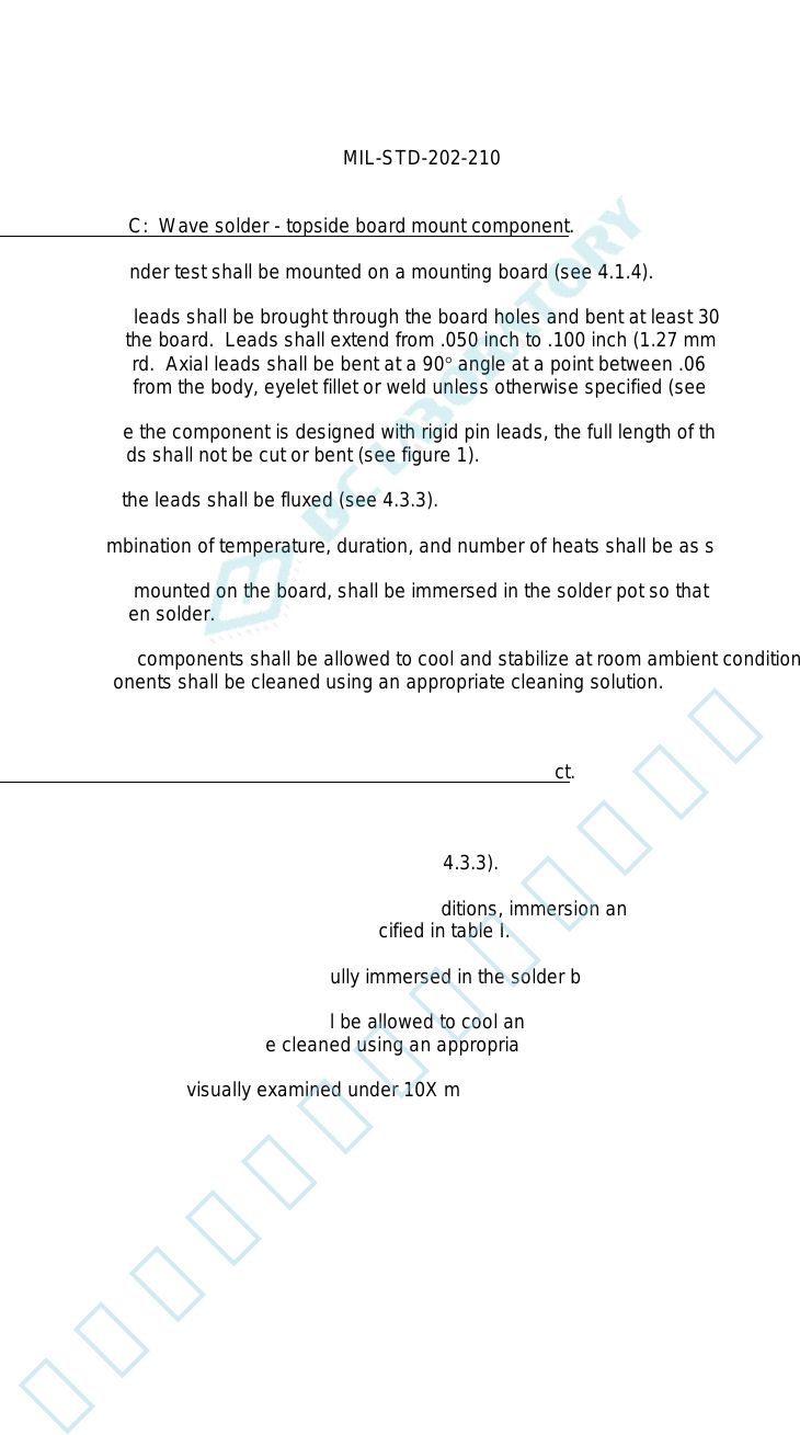
4.3.4.3 Test condition C: Wave solder - topside board mount component.
a. The component under test shall be mounted on a mounting board (see 4.1.4).
Wire leads: Wire leads shall be brought through the board holes and bent at least 30 degrees from a line
perpendicular to the board. Leads shall extend from .050 inch to .100 inch (1.27 mm to 2.54 mm) from the
bottom of the board. Axial leads shall be bent at a 90° angle at a point between .06 inch and .08 inch (1.5
mm and 2.1 mm) from the body, eyelet fillet or weld unless otherwise specified (see figure 1).
Pin leads: Where the component is designed with rigid pin leads, the full length of the termination shall be
retained. Pin leads shall not be cut or bent (see figure 1).
b. When specified, the leads shall be fluxed (see 4.3.3).
c. The specific combination of temperature, duration, and number of heats shall be as specified in table I.
d. The components, mounted on the board, shall be immersed in the solder pot so that the bottom of the board
floats on the molten solder.
e. After the float, the components shall be allowed to cool and stabilize at room ambient conditions. If flux was
used, the components shall be cleaned using an appropriate cleaning solution.
f. The components shall be visually examined under 10X magnification.
4.3.4.4 Test condition D: Wave solder - bottomside board mount product.
a. Place the component in an appropriate fixture (see 4.1.3).
b. When specified, the terminations shall be fluxed (see 4.3.3).
c. The specific combination of temperature, preheat conditions, immersion and emersion rates, immersion
duration, and number of heats shall be as specified in table I.
d. The component shall be preheated and fully immersed in the solder bath in accordance with 4.3.4.4c.
e. After the immersion, the component shall be allowed to cool and stabilize at room ambient conditions. If flux
was used, the component shall be cleaned using an appropriate cleaning solution.
f. The component shall be visually examined under 10X magnification.
4
北测(上海)电子科技有限公司
联系方式:xuyj@beice-sh.com 13917165676
MIL-STD-202-210
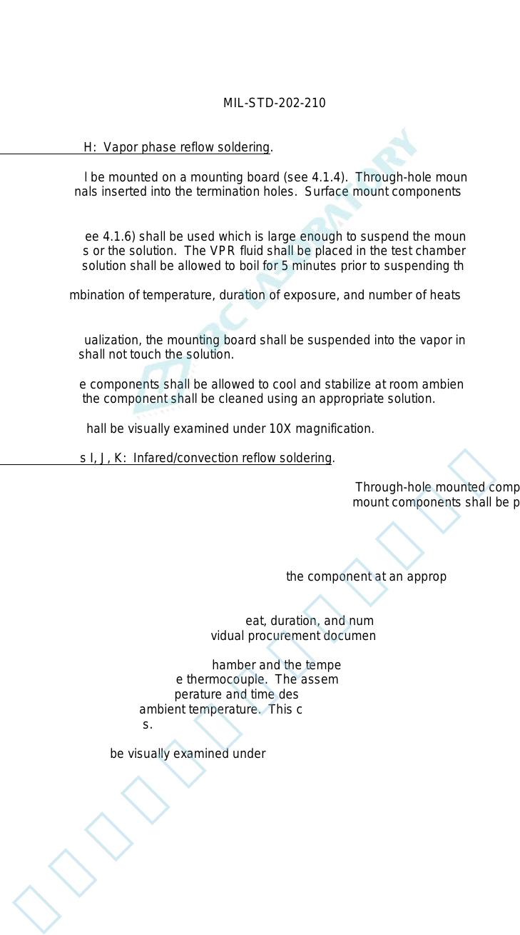
4.3.4.5 Test condition H: Vapor phase reflow soldering.
a. Components shall be mounted on a mounting board (see 4.1.4). Through-hole mounted components shall
have their terminals inserted into the termination holes. Surface mount components shall be placed on top of
the board.
b. A test chamber (see 4.1.6) shall be used which is large enough to suspend the mounting board without
touching the sides or the solution. The VPR fluid shall be placed in the test chamber and shall be heated until
it is boiling. The solution shall be allowed to boil for 5 minutes prior to suspending the mounting board.
c. The specific combination of temperature, duration of exposure, and number of heats shall be as specified in
table I.
d. After chamber equalization, the mounting board shall be suspended into the vapor in a horizontal plane. The
mounting board shall not touch the solution.
e. After the heat, the components shall be allowed to cool and stabilize at room ambient conditions. If a solder
paste was used, the component shall be cleaned using an appropriate solution.
f. The components shall be visually examined under 10X magnification.
4.3.4.6 Test conditions I, J, K: Infared/convection reflow soldering.
a. Components shall be mounted on a mounting board (see 4.1.4). Through-hole mounted components shall
have their terminals inserted into the termination holes. Surface mount components shall be placed on top of
the board.
b. A test chamber as specified in 4.1.6 shall be used.
c. A low mass thermocouple shall be attached tightly to the component at an appropriate position away from the
edges.
d. The specific combination of temperature, preheat, duration, and number of heats shall be as specified by test
condition I, J, or K in table I and the individual procurement document.
e. The board shall be placed into the test chamber and the temperature of the component ramped at a rate of
1°C/s to 4°C/s as measured by the thermocouple. The assembly shall be above 183°C for 90 seconds to 120
seconds and held at the final temperature and time designated by the test condition. The assembly shall then
be allowed to cool to room ambient temperature. This constitutes one heat cycle. The assembly shall be
exposed to three heat cycles.
f. The components shall be visually examined under 10X magnification.
5
北测(上海)电子科技有限公司
联系方式:xuyj@beice-sh.com 13917165676
MIL-STD-202-210
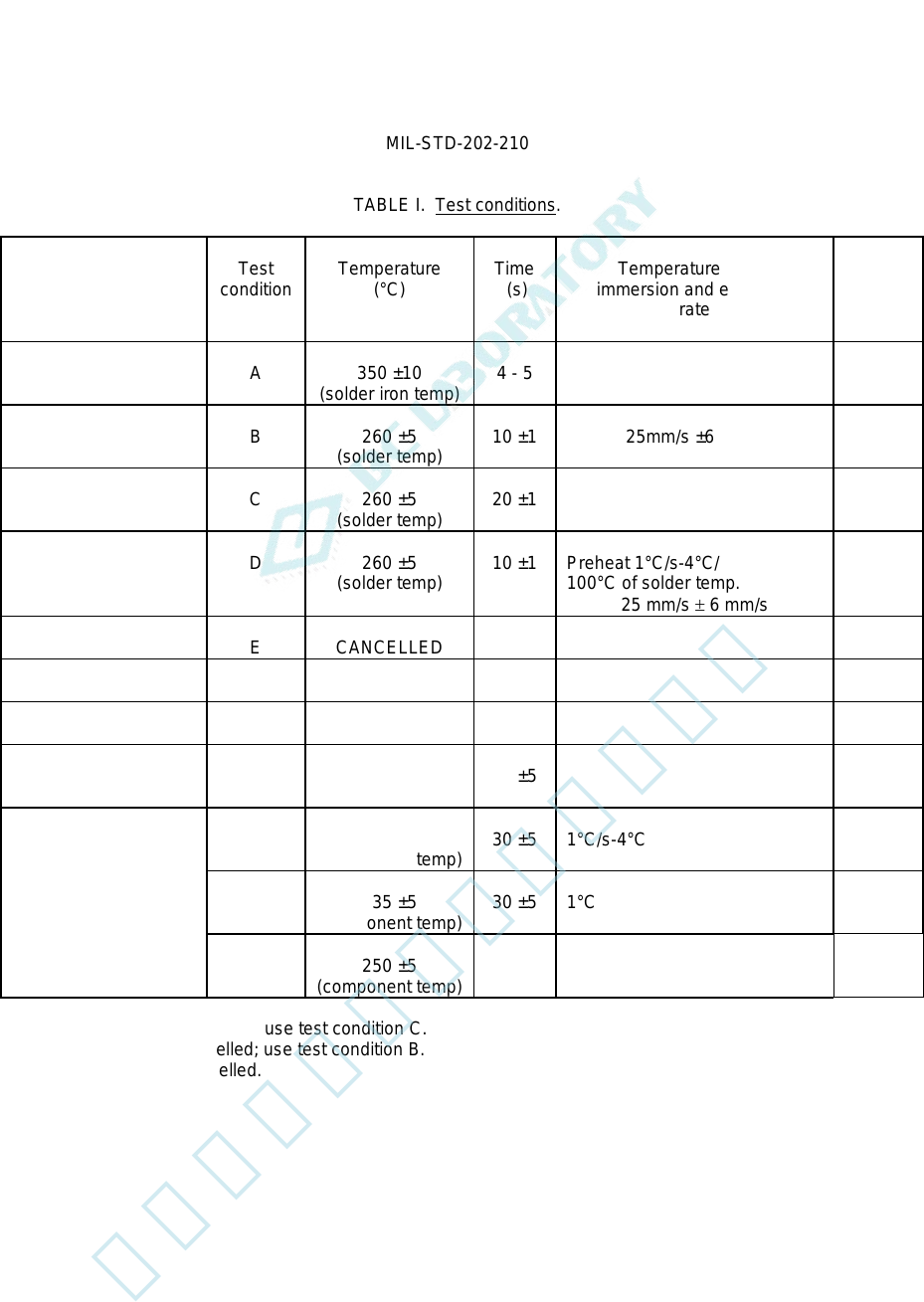
TABLE I. Test conditions.
Solder technique
simulation
Test
condition
Temperature
(°C)
Time
(s)
Temperature ramp/
immersion and emersion
rate
Number
of
heat
cycles
Solder iron
A
350 ±10
(solder iron temp)
4 - 5
1
Dip
B
260 ±5
(solder temp)
10 ±1
25mm/s ±6 mm/s
1
Wave: Topside
board-mount product
C
260 ±5
(solder temp)
20 ±1
1
Wave: Bottomside
board-mount product
D
260 ±5
(solder temp)
10 ±1
Preheat 1°C/s-4°C/s to within
100°C of solder temp.
25 mm/s ± 6 mm/s
1
E
CANCELLED
F
CANCELLED
G
CANCELLED
Vapor phase reflow
H
215 ±5
(vapor temp)
60 ±5
1
IR/convection reflow
I
215 ±5
(component temp)
30 ±5
1°C/s-4°C/s; time above 183°C,
90 s - 120 s
3
J
235 ±5
(component temp)
30 ±5
1°C/s-4°C/s; time above 183°C,
90 s - 120 s
3
K
250 ±5
(component temp)
30 ±5
1°C/s-4°C/s; time above 183°C,
90 s - 120 s
3
Test condition E is cancelled; use test condition C.
Test condition F is cancelled; use test condition B.
Test condition G is cancelled.
6
北测(上海)电子科技有限公司
联系方式:xuyj@beice-sh.com 13917165676