MIL-STD-202H.pdf - 第188页
MI L - S TD - 202 -2 12 M E TH O D 2 12 AC C EL ER AT I O N 1. SCOPE 1.1 P urpose . This te st i s per f or m e d f or t he p ur po s e o f det er m i ni n g t he ef f e c t s of a c c el er a tio n stress on component p…
MIL-STD-202-212
CONTENTS
PARAGRAPH PAGE
FOREWORD…………………………………………………………. ii
1. SCOPE 1
1.1 Purpose………………………………………….……..…………. 1
2. APPLICABLE DOCUMENTS 1
3. DEFINTIONS 1
4. GENERAL REQUIREMENTS 1
4.1 Apparatus.………………….…………………….…...…………. 1
4.2 Mounting accessories. …….…………………….…...…………. 1
4.3 Procedure…………………………………………………………. 1
4.3.1 Test condition A…….……………………………………………. 1
4.3.1 Test condition B…….……………………………………………. 1
4.3.1 Test condition C…….……………………………………………. 1
4.4 Measurements…..….……………………………………………. 1
5. DETAILED REQUIREMENTS 2
5.1 Summary……………………………………………………….… 2
6. NOTES 2
6.1 Supersession data………………………………………………. 2
iii
北测(上海)电子科技有限公司
联系方式:xuyj@beice-sh.com 13917165676
MIL-STD-202-212
METHOD 212
ACCELERATION
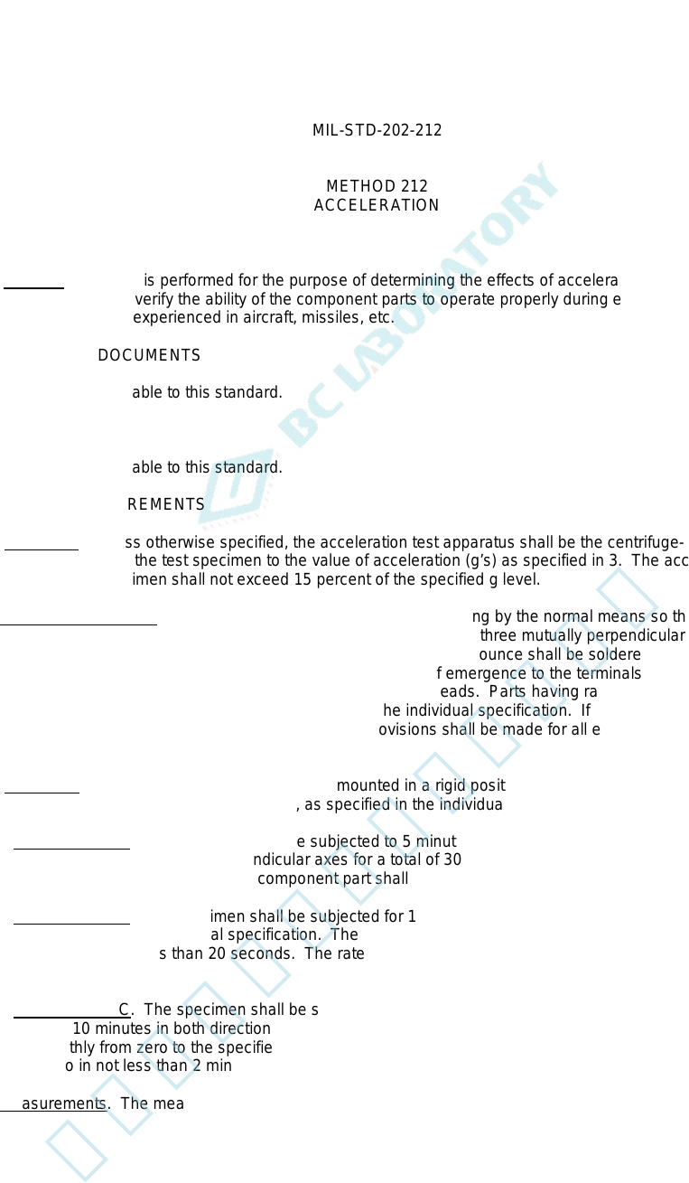
1. SCOPE
1.1 Purpose. This test is performed for the purpose of determining the effects of acceleration stress on
component parts, and to verify the ability of the component parts to operate properly during exposure to acceleration
stress such as would be experienced in aircraft, missiles, etc.
2. APPLICABLE DOCUMENTS
This section not applicable to this standard.
3. DEFINTIONS
This section not applicable to this standard.
4. GENERAL REQUIREMENTS
4.1. Apparatus. Unless otherwise specified, the acceleration test apparatus shall be the centrifuge-type and shall
be capable of subjecting the test specimen to the value of acceleration (g’s) as specified in 3. The acceleration
gradient across the specimen shall not exceed 15 percent of the specified g level.
4.2 Mounting accessories. Provisions shall be made to permit mounting by the normal means so that the
specimen can be tested in both directions, 180 degrees apart, of each of three mutually perpendicular axes, unless
otherwise specified. Parts with axial terminations weighing less than 0.5 ounce shall be soldered to stand-off
terminals, leaving a distance of 0.2 inch to 0.3 inch from the point of emergence to the terminals. Parts weighing 0.5
ounce and more shall be clamped so as to avoid any stress on the leads. Parts having radial leads and those of
unusual mass distribution shall be mounted as specified in the individual specification. If loading, actuating, or
polarizing currents are required, they shall be specified. Provisions shall be made for all electrical connections to be
secure.
4.3. Procedure. The specimen under test shall be mounted in a rigid position as specified in 4.2 and shall be
subjected to one of the following test conditions, as specified in the individual specification.
4.3.1 Test condition A. The specimen shall be subjected to 5 minutes acceleration of the specified "g" level in both
directions of each of three mutually perpendicular axes for a total of 30 minutes at either 20, 50, or 100g level. The
acceleration measured at any point of the component part shall not exceed 15 percent of the "g" level.
4.3.2 Test condition B. The specimen shall be subjected for 1 minute at nominally 10,000 or 20,000g in the
direction as specified in the individual specification. The rate of acceleration shall be increased smoothly from zero to
the specified value in not less than 20 seconds. The rate of acceleration shall be decreased smoothly to zero in not
less than 20 seconds.
4.3.3 Test condition C. The specimen shall be subjected to the value of acceleration specified in the individual
specification for 10 minutes in both directions of each of three mutually perpendicular axes. The acceleration shall be
increased smoothly from zero to the specified value in approximately 2 minutes. The acceleration shall be decreased
smoothly to zero in not less than 2 minutes.
4.4 Measurements. The measurements made before, during, or after the test shall be as specified.
1
北测(上海)电子科技有限公司
联系方式:xuyj@beice-sh.com 13917165676
MIL-STD-202-212
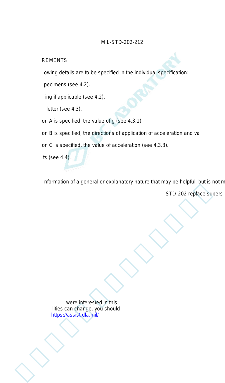
5. DETAILED REQUIREMENTS
5.1 Summary. The following details are to be specified in the individual specification:
a. Mounting of specimens (see 4.2).
b. Electrical loading if applicable (see 4.2).
c. Test condition letter (see 4.3).
d. If test condition A is specified, the value of g (see 4.3.1).
e. If test condition B is specified, the directions of application of acceleration and value of g (see 4.3.2).
f. If test condition C is specified, the value of acceleration (see 4.3.3).
g. Measurements (see 4.4).
6. NOTES
(This section contains information of a general or explanatory nature that may be helpful, but is not mandatory.)
6.1 Supersession data. The main body and 38 parts of this revision of MIL-STD-202 replace superseded MIL-STD-
202.
Custodians: Preparing activity:
Army - CR DLA - CC
Navy - EC
Air Force - 85 (Project 59GP-2015-026)
DLA - CC
Review activities:
Army - AR, AT, AV, CR4, MI, SM, TE
Navy - AS, OS, SH
Air Force - 19, 99
NSA - NS
NOTE: The activities listed above were interested in this document as of the date of this document. Since
organizations and responsibilities can change, you should verify the currency of the information above using the
ASSIST Online database at https://assist.dla.mil/
2
北测(上海)电子科技有限公司
联系方式:xuyj@beice-sh.com 13917165676