MIL-STD-202H.pdf - 第181页
MI L - S TD - 202 -2 11 FIGURE 2. Test condit ion B . F IGURE 3. Test cond ition C . 4 北测(上海)电子科技有限公 司 联系方式:xuyj@beice-sh.com 13917165676
MIL-STD-202-211
4.2.4.2 Application of torsion. The body of the component part or the clamped terminal shall be rotated through
360° about the original axis of the bent terminal, in alternating directions, for a total of three rotations 1080°, at the
rate of approximately 5 seconds per rotation.
4.2.5 Test condition E (torque test).
4.2.5.1 Direction and application of torque. The torque shall be applied clockwise and then counterclockwise in a
plane perpendicular to the axis of the terminal, as shown on figure 5.
4.2.5.2 Duration of applied force. The force shall be applied gradually to the terminal and then maintained for a
period of 5 to 15 seconds.
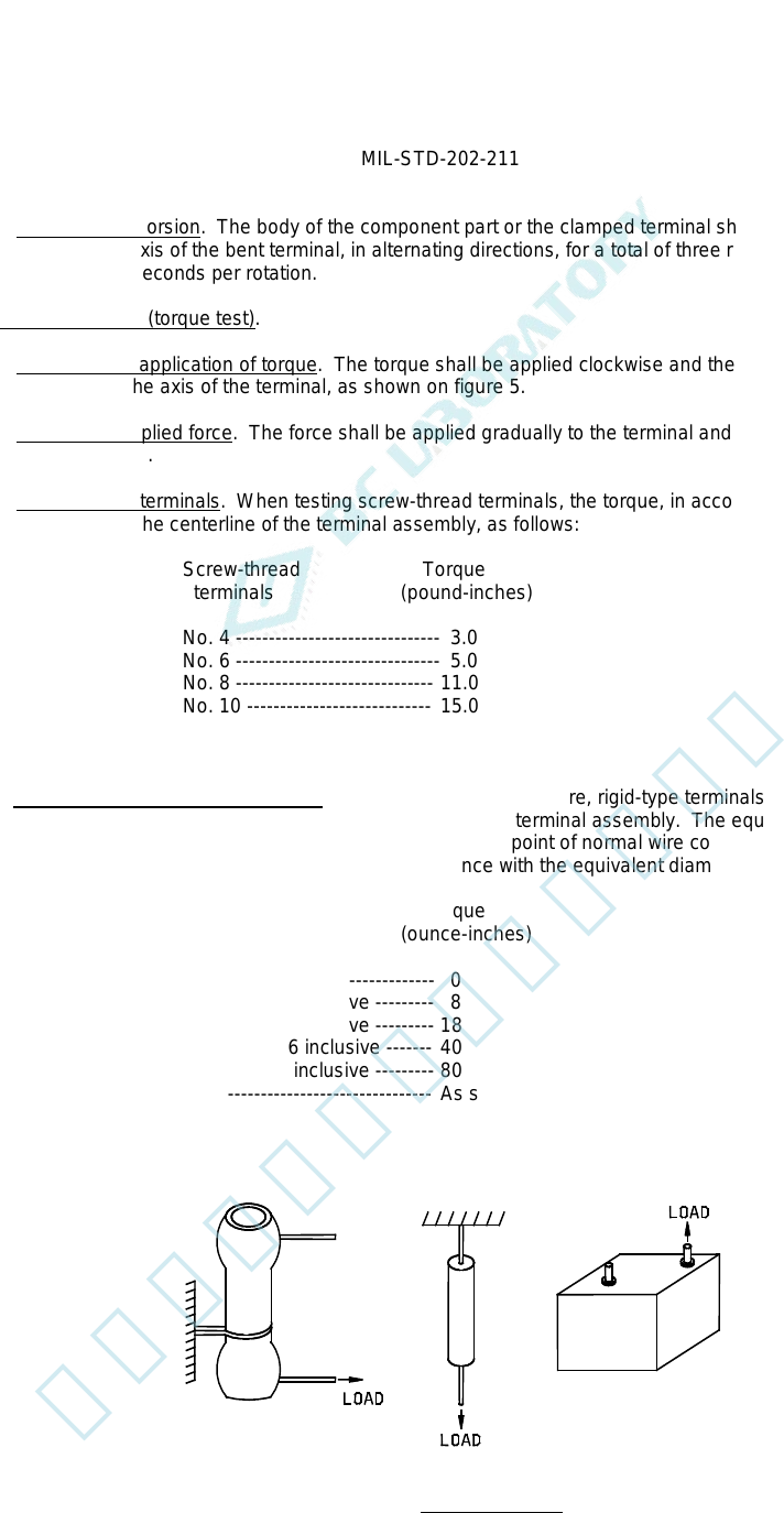
4.2.5.3 Screw-thread terminals. When testing screw-thread terminals, the torque, in accordance with the terminal
size, shall be applied to the centerline of the terminal assembly, as follows:
Screw-thread Torque
terminals (pound-inches)
No. 4 ------------------------------- 3.0
No. 6 ------------------------------- 5.0
No. 8 ------------------------------ 11.0
No. 10 ---------------------------- 15.0
No. 12 ---------------------------- 24.0
1/4 inch -------------------------- 32.0
4.2.5.4 Other non-wire, rigid-type terminals. When testing other non-wire, rigid-type terminals, the applied torque is
dependent on the equivalent diameter of the external portion of the terminal assembly. The equivalent diameter is
defined as equal to twice the distance from the terminal axis to the point of normal wire connection, as shown in the
examples on figure 6. The torque shall be applied in accordance with the equivalent diameter, as follows:
Equivalent diameter Torque
(inch) (ounce-inches)
1/16 or less --------------------- 0
>1/16 to 1/8 inclusive --------- 8
>1/8 to 3/16 inclusive --------- 18
>3/16 to 5/16 inclusive ------- 40
>5/16 to 1/2 inclusive --------- 80
>1/2 ------------------------------- As specified in the individual specification
FIGURE 1. Test condition A.
3
北测(上海)电子科技有限公司
联系方式:xuyj@beice-sh.com 13917165676
MIL-STD-202-211
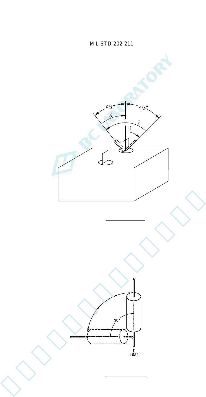
FIGURE 2. Test condition B.
FIGURE 3. Test condition C.
4
北测(上海)电子科技有限公司
联系方式:xuyj@beice-sh.com 13917165676
MIL-STD-202-211
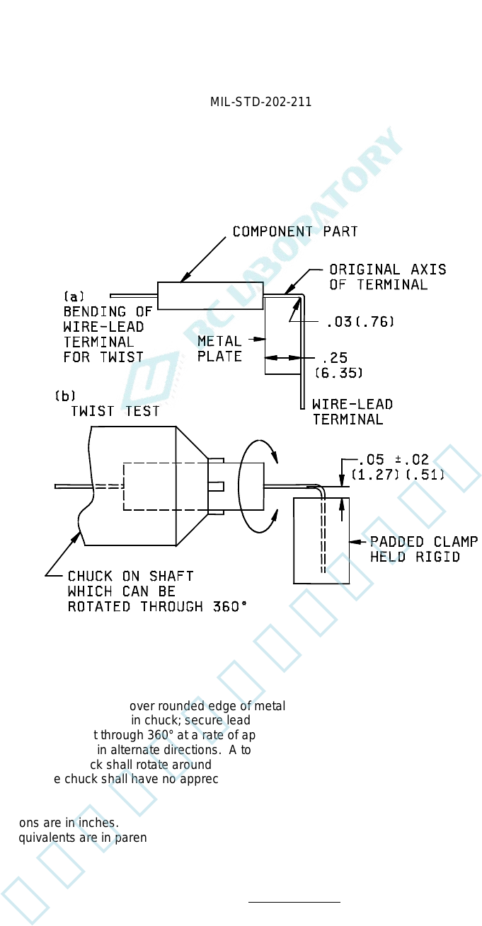
STEP 1. Bend lead with fingers, over rounded edge of metal plate as shown in (a).
STEP 2. Center component part in chuck; secure lead in clamp as shown in (b).
STEP 3. Rotate chuck part through 360° at a rate of approximately 5 seconds per 360° rotation. Successive
rotations shall be in alternate directions. A total of three such 360° rotations shall be performed. During
this test, the chuck shall rotate around an axis which is fixed with respect to the padded clamp, or vice
versa. The chuck shall have no appreciable end play during rotation.
NOTES:
1. Dimensions are in inches.
2. Metric equivalents are in parentheses and are given for general information only.
FIGURE 4. Test condition D.
5
北测(上海)电子科技有限公司
联系方式:xuyj@beice-sh.com 13917165676