MIL-STD-202H.pdf - 第274页
MI L - S TD - 202 - 308 4.2.3 Deter mination of t he " m i c r ov ol t s - per - vo l t - in -a - de c ade " i ndex . T he c ur r ent - noi s e i nde x to be co mpared with the require d index (see 5 ) s ha l l…
MIL-STD-202-308
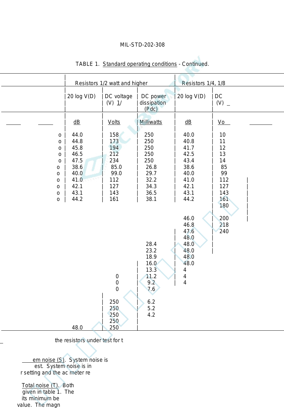
TABLE 1. Standard operating conditions - Continued.
| | | |
| Resistance | Resistors 1/2 watt and higher | Resistors 1/4, 1/8, and 1/10 watt |
| | | | | | | | |
| Resistor | Isolation | 20 log V(D) | DC voltage | DC power | 20 log V(D) | DC voltage | DC power |
| under | resistor | | (V) 1/ | dissipation | | (V) 1/ | dissipation |
| test (Rt) | (Rm) | | | (Pdc) | | | (Pdc) |
| | | | | | | | |
| Ohms | Ohms | dB | Volts | Milliwatts | dB | Volts | Milliwatts |
| | | | | | | | |
| 0.10 mego | 0.10 mego | 44.0 | 158 | 250 | 40.0 | 100 | 100 |
| 0.12 mego | 0.10 mego | 44.8 | 173 | 250 | 40.8 | 110 | 100 |
| 0.15 mego | 0.10 mego | 45.8 | 194 | 250 | 41.7 | 122 | 100 |
| 0.18 mego | 0.10 mego | 46.5 | 212 | 250 | 42.5 | 134 | 100 |
| 0.22 mego | 0.10 mego | 47.5 | 234 | 250 | 43.4 | 148 | 100 |
| 0.27 mego | 1.0 mego | 38.6 | 85.0 | 26.8 | 38.6 | 85.0 | 26.8 |
| 0.33 mego | 1.0 mego | 40.0 | 99.0 | 29.7 | 40.0 | 99.0 | 29.7 |
| 0.39 mego | 1.0 mego | 41.0 | 112 | 32.2 | 41.0 | 112 | 32.2 |
| 0.47 mego | 1.0 mego | 42.1 | 127 | 34.3 | 42.1 | 127 | 34.3 |
| 0.56 mego | 1.0 mego | 43.1 | 143 | 36.5 | 43.1 | 143 | 36.5 |
| 0.68 mego | 1.0 mego | 44.2 | 161 | 38.1 | 44.2 | 161 | 38.1 |
| 0.82 mego | 1.0 mego | 45.1 | 180 | 39.5 | 45.1 | 180 | 39.5 |
| | | | | | | | |
| 1.0 mego | 1.0 mego | 46.0 | 200 | 40.0 | 46.0 | 200 | 40.0 |
| 1.2 mego | 1.0 mego | 46.8 | 218 | 39.6 | 46.8 | 218 | 39.6 |
| 1.5 mego | 1.0 mego | 47.6 | 240 | 38.4 | 47.6 | 240 | 38.4 |
| 1.8 mego | 1.0 mego | 48.0 | 250 | 34.7 | 48.0 | 250 | 34.7 |
| 2.2 mego | 1.0 mego | 48.0 | 250 | 28.4 | 48.0 | 250 | 28.4 |
| 2.7 mego | 1.0 mego | 48.0 | 250 | 23.2 | 48.0 | 250 | 23.2 |
| 3.3 mego | 1.0 mego | 48.0 | 250 | 18.9 | 48.0 | 250 | 18.9 |
| 3.9 mego | 1.0 mego | 48.0 | 250 | 16.0 | 48.0 | 250 | 16.0 |
| 4.7 mego | 1.0 mego | 48.0 | 250 | 13.3 | 48.0 | 250 | 13.3 |
| 5.6 mego | 1.0 mego | 48.0 | 250 | 11.2 | 48.0 | 250 | 11.2 |
| 6.8 mego | 1.0 mego | 48.0 | 250 | 9.2 | 48.0 | 250 | 9.2 |
| 8.2 mego | 1.0 mego | 48.0 | 250 | 7.6 | 48.0 | 250 | 7.6 |
| | | | | | | | |
| 10 mego | 1.0 mego | 48.0 | 250 | 6.2 | 48.0 | 250 | 6.2 |
| 12 mego | 1.0 mego | 48.0 | 250 | 5.2 | 48.0 | 250 | 5.2 |
| 15 mego | 1.0 mego | 48.0 | 250 | 4.2 | 48.0 | 250 | 4.2 |
| 18 mego | 1.0 mego | 48.0 | 250 | 3.5 | 48.0 | 250 | 3.5 |
| 22 mego | 1.0 mego | 48.0 | 250 | 2.8 | 48.0 | 250 | 2.8 |
1/ DC voltage across the resistors under test for the measurement of total noise.
4.2.2.2 System noise (S). System noise is the background noise present when direct current is not present in the
resistor under test. System noise is indicated after turning off the calibration voltage. The algebraic sum of the ac
attenuator setting and the ac meter reading gives the magnitude of system noise, S, in dB.
4.2.2.3 Total noise (T). Both the dc voltage and the total noise are measured simultaneously. The value of dc
voltage is given in table 1. The application of excessive dc voltage should be avoided by setting the dc voltage
control to its minimum before applying the voltage, and when the voltage is applied, it should be increased to the
desired value. The magnitude of the dc voltage is given by the sum, D, of the dc attenuator setting and the dc meter
reading in dB. D equals 20 log V, where V is the dc voltage, in volts, applied to the terminals of the resistor under
test. The associated noise measurement indicates the total noise present, i.e., the quadratic sum of the system noise
and the current noise. This total noise is indicated by T, in dB.
5
北测(上海)电子科技有限公司
联系方式:xuyj@beice-sh.com 13917165676
MIL-STD-202-308
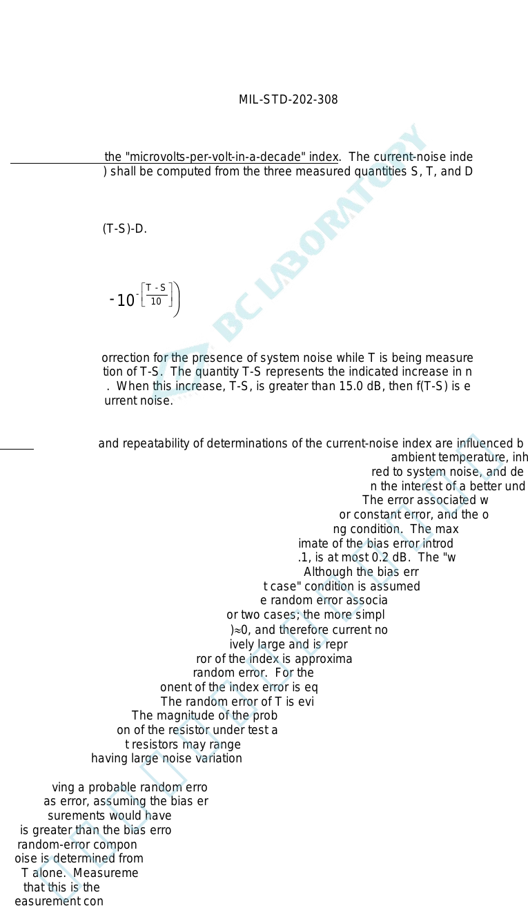
4.2.3 Determination of the "microvolts-per-volt-in-a-decade" index. The current-noise index to be compared with
the required index (see 5) shall be computed from the three measured quantities S, T, and D, in accordance with the
following formula:
(Index), in dB = T-f(T-S)-D.
Where:
10
- 1 10 - = S)- f(T
10
S- T
-
log
The quantity f(T-S) is a correction for the presence of system noise while T is being measured. Values of f(T-S) are
given in table 2 as a function of T-S. The quantity T-S represents the indicated increase in noise resulting from the
presence of direct current. When this increase, T-S, is greater than 15.0 dB, then f(T-S) is essentially zero, and T
alone is the measure of current noise.
4.3 Errors. Accuracy and repeatability of determinations of the current-noise index are influenced by the combined
effects of many factors including the following - characteristics of the test set, ambient temperature, inherent
fluctuations in current noise, relative magnitude of current noise as compared to system noise, and delay between the
application of dc voltage and observation of meter deflection. Therefore, in the interest of a better understanding of
the significance of the measurement, a discussion of errors is included. The error associated with the determination
of the index is a function of two independent errors, one a bias-type or constant error, and the other a random-type or
variable error. The bias error is constant for any particular measuring condition. The maximum bias error introduced
by the test set should not exceed 0.4 dB. A conservative estimate of the bias error introduced by the permissible
departure of ambient temperature from 25°C as stated in 4.2.1, is at most 0.2 dB. The "worst case" bias error for
these two factors is the sum of their absolute values, 0.6 dB. Although the bias error for any particular measurement
is not known, for purposes of this discussion the "worst case" condition is assumed, and 0.6 dB will be considered the
magnitude of bias error associated with the index. The random error associated with the index is that of the current
noise, [T-f(T-S)]. The index will be considered for two cases; the more simple case where the current noise is
relatively large, i.e., T-S>15.0 dB for which f(T-S)≈0, and therefore current noise is represented by T alone; and the
second case where the current noise is not relatively large and is represented by [T-f(T-S)], with f(T-S) being
significant. In either case, the probable error of the index is approximately equal to the error component which
predominates, whether it be bias error or random error. For the first case, the only significant quantity which varies is
T, therefore the random-error component of the index error is equal to the random error associated with the
measurement of the total noise, T. The random error of T is evidenced by fluctuations of the meter pointer and tends
to have a normal distribution. The magnitude of the probable random error of T cannot be given explicitly because its
value is necessarily a function of the resistor under test and must be determined from measurements. The probable
random error of T for different resistors may range from values as low as approximately 0.2 dB to values as high as
several dB in resistors having large noise variations.
For resistors having a probable random error of T less than 0.6 dB, the probable error of the index is approximately
equal to the bias error, assuming the bias error is the "worst case", i.e., 0.6 dB. This means that on the average, one-
half of the measurements would have an error no greater than 0.6 dB. On the other hand, when the probable random
error of T is greater than the bias error, the probable error of the index is equal to that of T. For the second case, the
probable random-error component of the index is greater than that of T alone. This follows because the magnitude of
current noise is determined from the difference between two measurements, T and S, each of which fluctuates, rather
than from T alone. Measurements indicate that the probable random error of S should be in the order of 0.2 dB.
Assuming that this is the case, the probable random-error component of the index is approximately double that of T
for the measurement condition T-S = 3 dB, and approximately four times that of T for the condition T-S = 1.5 dB. The
limit of sensitivity for measuring the current-noise index is approached as the current noise approaches values too
small to cause an increase as much as 1.0 dB, i.e., T-S equal to 1.0 dB. However, the test method may serve as a
qualitative means for comparing resistors having relatively low values of current noise where T-S is less than 1.0 dB.
6
北测(上海)电子科技有限公司
联系方式:xuyj@beice-sh.com 13917165676
MIL-STD-202-308
Another possible source of measurement uncertainty is the transitory variations in current noise which may
immediately follow application of dc voltage. Certain types of resistors tend to display very little, if any, transitory
variations, whereas other types tend to display such variations to a measurable degree. For those resistors which
exhibit such variations, the current noise usually settles to a more stable value after a short time, from 1 to several
seconds. In some cases, the current-noise variations may continue to be relatively large and unstable for extended
periods of time. Such resistors are usually very noisy. By adhering to the precautions regarding the procedures
stated in 1.1, the effects of such variations on repeated measurements are reduced.
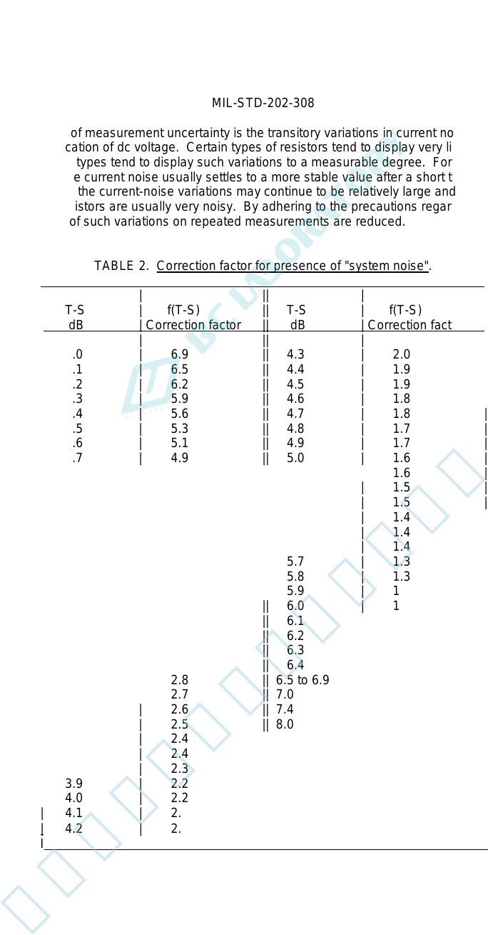
TABLE 2. Correction factor for presence of "system noise".
| | || | |
| T-S | f(T-S) || T-S | f(T-S) |
| dB | Correction factor || dB | Correction factor |
| | || | |
| 1.0 | 6.9 || 4.3 | 2.0 |
| 1.1 | 6.5 || 4.4 | 1.9 |
| 1.2 | 6.2 || 4.5 | 1.9 |
| 1.3 | 5.9 || 4.6 | 1.8 |
| 1.4 | 5.6 || 4.7 | 1.8 |
| 1.5 | 5.3 || 4.8 | 1.7 |
| 1.6 | 5.1 || 4.9 | 1.7 |
| 1.7 | 4.9 || 5.0 | 1.6 |
| 1.8 | 4.7 || 5.1 | 1.6 |
| 1.9 | 4.5 || 5.2 | 1.5 |
| 2.0 | 4.3 || 5.3 | 1.5 |
| 2.1 | 4.1 || 5.4 | 1.4 |
| 2.2 | 3.9 || 5.5 | 1.4 |
| 2.3 | 3.8 || 5.6 | 1.4 |
| 2.4 | 3.6 || 5.7 | 1.3 |
| 2.5 | 3.5 || 5.8 | 1.3 |
| 2.6 | 3.4 || 5.9 | 1.3 |
| 2.7 | 3.3 || 6.0 | 1.2 |
| 2.8 | 3.2 || 6.1 | 1.2 |
| 2.9 | 3.1 || 6.2 | 1.2 |
| 3.0 | 3.0 || 6.3 | 1.1 |
| 3.1 | 2.9 || 6.4 | 1.1 |
| 3.2 | 2.8 || 6.5 to 6.9 | 1.0 |
| 3.3 | 2.7 || 7.0 to 7.3 | 0.9 |
| 3.4 | 2.6 || 7.4 to 7.9 | 0.8 |
| 3.5 | 2.5 || 8.0 to 8.5 | 0.7 |
| 3.6 | 2.4 || 8.6 to 9.3 | 0.6 |
| 3.7 | 2.4 || 9.4 to 9.9 | 0.5 |
| 3.8 | 2.3 || 10.0 to 11.5 | 0.4 |
| 3.9 | 2.2 || 11.6 to 12.7 | 0.3 |
| 4.0 | 2.2 || 12.8 to 14.5 | 0.2 |
| 4.1 | 2.1 || 14.6 to 15.0 | 0.1 |
| 4.2 | 2.0 || M15.0 | ≈ 0 I
I I
7
北测(上海)电子科技有限公司
联系方式:xuyj@beice-sh.com 13917165676