MIL-STD-202H.pdf - 第90页
MI L - S TD - 202 - 112 4.4 .4.3.2. 2.4 Spe cif ic p r oc e dur e IIIb . T he dev i c es s h al l be p l ac ed i n r adi oac t i v e t r a c er g a s activation tan k. The activation chamber may b e pa r t i al l y f i l…
MIL-STD-202-112
4.4.4.3.2.2 Procedure IIIb.
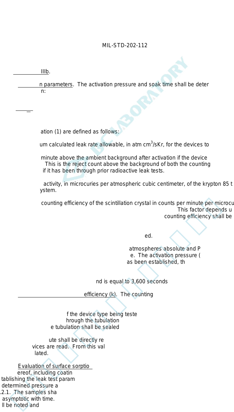
4.4.4.3.2.2.1 Activation parameters. The activation pressure and soak time shall be determined in accordance
with the following equation:
tPskT
R
s
Q =
The parameters of equation (1) are defined as follows:
Q
S
= The maximum calculated leak rate allowable, in atm cm
3
/sKr, for the devices to be tested.
R = Counts per minute above the ambient background after activation if the device leak rate were exactly
equal to Q
S
. This is the reject count above the background of both the counting equipment and the
component, if it has been through prior radioactive leak tests.
s = The specific activity, in microcuries per atmospheric cubic centimeter, of the krypton 85 tracer gas in the
activation system.
k = The overall counting efficiency of the scintillation crystal in counts per minute per microcurie of krypton
85 in the internal void of the specific component being evaluated. This factor depends upon component
configuration and dimensions of the scintillation crystal. The counting efficiency shall be determined in
accordance with 4.4.4.3.2.2.2.
T = Soak time, in hours, that the devices are to be activated.
_
P = P
e
2
- P
i
2
, where P
e
is the activation pressure in atmospheres absolute and P
i
is the original internal
pressure of the devices in atmospheres absolute. The activation pressure (P
e
) may be established by
specification or if a convenient soak time (T) has been established, the activation pressure (P
e
) can be
adjusted to satisfy equation (1).
t = Conversion of hours to seconds and is equal to 3,600 seconds per hour.
4.4.4.3.2.2.2 Determination of counting efficiency (k). The counting efficiency (k) of equation in 4.4.4.3.2.2.1 shall
be determined as follows:
a. Five representative units of the device type being tested shall be tubulated and the internal void of the
device shall be backfilled through the tubulation with a known volume and known specific activity of krypton
85 tracer gas and the tubulation shall be sealed off.
b. The counts per minute shall be directly read in the shielded scintillation crystal of the counting station in
which the devices are read. From this value, the counting efficiency, in counts per minute per microcurie,
shall be calculated.
4.4.4.3.2.2.3 Evaluation of surface sorption. All device encapsulations consisting of glass, metal, and ceramic or
combinations thereof, including coatings and external sealants, shall be evaluated for surface sorption of krypton 85
before establishing the leak test parameters. Representative samples of the questionable material shall be subjected
to the predetermined pressure and time conditions established for the device configuration as specified by
4.4.4.3.2.2.1. The samples shall then be counted every 10 minutes, with count rate noted, until the count rate
becomes asymptotic with time. (This is the point in time at which surface sorption is no longer a problem.) This time
lapse shall be noted and shall determine the "wait time" specified in 4.4.4.3.2.2.4.
7
北测(上海)电子科技有限公司
联系方式:xuyj@beice-sh.com 13917165676
MIL-STD-202-112
4.4.4.3.2.2.4 Specific procedure IIIb. The devices shall be placed in radioactive tracer gas activation tank. The
activation chamber may be partially filled with inert material to reduce pumpdown time. The tank shall be evacuated
to 0.5 torr. The devices shall be subjected to a minimum of 2 atmospheres absolute pressure of krypton 85/dry
nitrogen mixture for the time necessary to satisfy the equation. Actual pressure and soak time shall be determined in
accordance with 4.4.4.3.2.2.1. The R value in counts per minute shall be not less than 600 above ambient
background. The krypton 85/dry nitrogen gas mixture shall be evacuated to storage until 0.5 torr vacuum exists in the
activation tank. This evacuation shall be completed within 3 minutes maximum. The activation tank shall then be
backfilled with air (air wash). The devices shall then be removed from the activation tank and leak tested within 1
hour after gas exposure with a scintillation-crystal-equipped counting station. Device encapsulations that come under
the requirements of 4.4.4.3.2.2.3 shall be exposed to ambient air for a time not less than the "wait time" determined
by 4.4.4.3.2.2.3. In no case will the time between removal from the activation chamber and test exceed 1 hour. This
exposure shall be performed after gas exposure but before determining leak rate with the counting station. Device
encapsulations that do not come under the requirements of 4.4.4.3.2.2.3 may be tested without a "wait time". (The
number of devices removed from pressurization for leak testing shall be limited such that the test of the last device
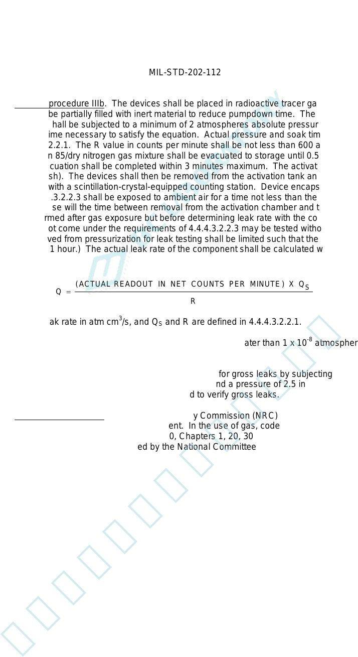
can be completed within 1 hour.) The actual leak rate of the component shall be calculated with the following
equation:
R
QXMINUTE
PERCOUNTSNETIN
READOUTACTUAL
Q
S
)(
=
Where Q = Actual leak rate in atm cm
3
/s, and Q
S
and R are defined in 4.4.4.3.2.2.1.
Unless otherwise specified, devices that exhibit a leak rate equal to or greater than 1 x 10
-8
atmospheric cubic
centimeters of krypton 85 per second shall be considered a failure.
Upon completion of this procedure, the specimen shall be checked for gross leaks by subjecting the specimen either
to test condition A, B, or D. Water, at room ambient temperature and a pressure of 2.5 inches (63.5 mm) of mercury,
may be used in place of silicone oil, if test condition B is used to verify gross leaks.
4.4.4.3.2.2.5 Personnel precautions. A Nuclear Regulatory Commission (NRC) license is necessary for
possession and use of the krypton 85 leak-test equipment. In the use of gas, code of Federal regulations Nuclear
Regulatory Commission Rules and Regulations, Title 10, Chapters 1, 20, 30, 31, and 32 should be followed and the
maximum permissible tolerance levels prescribed by the National Committee on Radiological Protection should be
observed.
8
北测(上海)电子科技有限公司
联系方式:xuyj@beice-sh.com 13917165676
MIL-STD-202-112
4.4.4.3.2.3 Procedure IIIc. Values for bomb pressure exposure time and dwell time shall be chosen such that
actual measured tracer gas leak rate (R
1
) reading obtained for the device under test (if defective) will be greater than
the minimum detection sensitivity capability of the mass spectrometer. The devices shall be subjected to a minimum
of 2 atmospheres absolute of helium atmosphere. If the chosen dwell time (t
z
) is greater than 60 minutes, graphs
shall be plotted to determine an R1 value which will assure overlap with the selected gross leak test condition. The
chosen values, in conjunction with the value of the internal volume of the device package to be tested and the
maximum equivalent standard leak rate (L) limit (as shown below or as specified in the applicable procurement
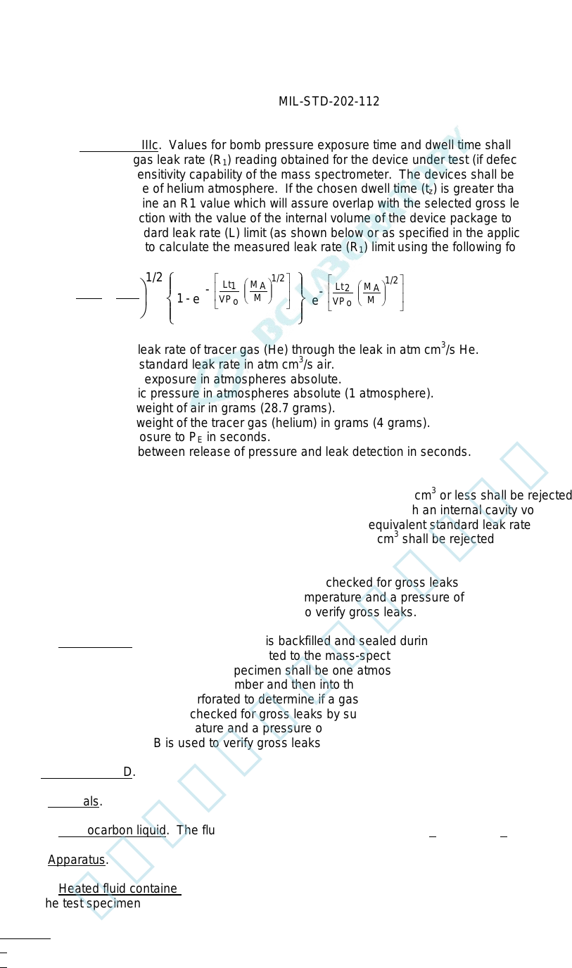
document), shall be used to calculate the measured leak rate (R
1
) limit using the following formula:
e
-
e
-
- 1
M
M
A
1/2
P
LP
=
R
M
M
A
1/2
VP
o
Lt
2
M
M
A
1/2
VP
o
Lt
1
O
E
1
R
1
= The measured leak rate of tracer gas (He) through the leak in atm cm
3
/s He.
L = The equivalent standard leak rate in atm cm
3
/s air.
P
E
= The pressure of exposure in atmospheres absolute.
P
O
= The atmospheric pressure in atmospheres absolute (1 atmosphere).
M
A
= The molecular weight of air in grams (28.7 grams).
M = The molecular weight of the tracer gas (helium) in grams (4 grams).
t
1
= The time of exposure to P
E
in seconds.
t
2
= The dwell time between release of pressure and leak detection in seconds.
V = The internal volume of the device package cavity in cubic centimeters.
Unless otherwise specified, devices with an internal cavity volume of 0.01 cm
3
or less shall be rejected if the
equivalent standard leak rate (L) exceeds 5 x 10
-8
atm cm
3
/s. Devices with an internal cavity volume greater than
0.01 cm
3
and equal to or less than 0.4 cm
3
shall be rejected if the equivalent standard leak rate (L) exceeds 1 x 10
-7
atm cm
3
/s. Devices with an internal cavity volume greater than 0.4 cm
3
shall be rejected if the equivalent standard
leak rate (L) exceeds 1 x 10
-6
atm cm
3
/s.
Upon completion of this procedure, the specimen shall be checked for gross leaks by subjecting the specimen either
to test condition A, B, or D. Water, at room ambient temperature and a pressure of 2.5 inches of mercury, may be
used in place of silicone oil, if test condition B is used to verify gross leaks.
4.4.4.4 Procedure IV. The specimen, which is backfilled and sealed during production with a known percentage of
tracer gas, shall be placed in a chamber connected to the mass-spectrometer-type leak detector, and the chamber
evacuated. The internal pressure of the specimen shall be one atmosphere or greater. If a leak exists, the gas
passes through the specimen into the chamber and then into the leak detector which will read the leakage rate. If
specified, the specimen shall be perforated to determine if a gas is actually present. Upon completion of this
procedure, the specimen shall be checked for gross leaks by subjecting the specimen either to test condition A, B, or
D. Water, at room ambient temperature and a pressure of 2.5 inches (63.5 mm) of mercury, may be used in place of
silicone oil, if test condition B is used to verify gross leaks.
4.5. Test condition D.
4.5.1 Materials.
4.5.1.1 Fluorocarbon liquid. The fluid shall be D02, D02-TS, D03, FC-40 1/ or FC-43 2/.
4.5.2 Apparatus.
4.5.2.1 Heated fluid container. The container for the fluid shall be made of pyrex glass and shall be sufficient size
to hold the test specimen in the fluid and to maintain a temperature of 125°C ±5°C (257°F ±9°F).
1/ D02, D02-TS, and D03 are the registered trade mark of Ausimont (Division of Montedison).
2/ Minnesota Mining Co. (3M) registered trade name.
9
北测(上海)电子科技有限公司
联系方式:xuyj@beice-sh.com 13917165676