MIL-STD-202H.pdf - 第291页
MI L - S TD - 202 -3 10 NOTES: 1. The square - w ave pu l s e gen er at or an d o s c i l l os c o pe shall have an a ccuracy of ±3 percent or better. 2. The ratio o f off - time t o d e te c ti o n - t i m e s hal l be …
MIL-STD-202-310
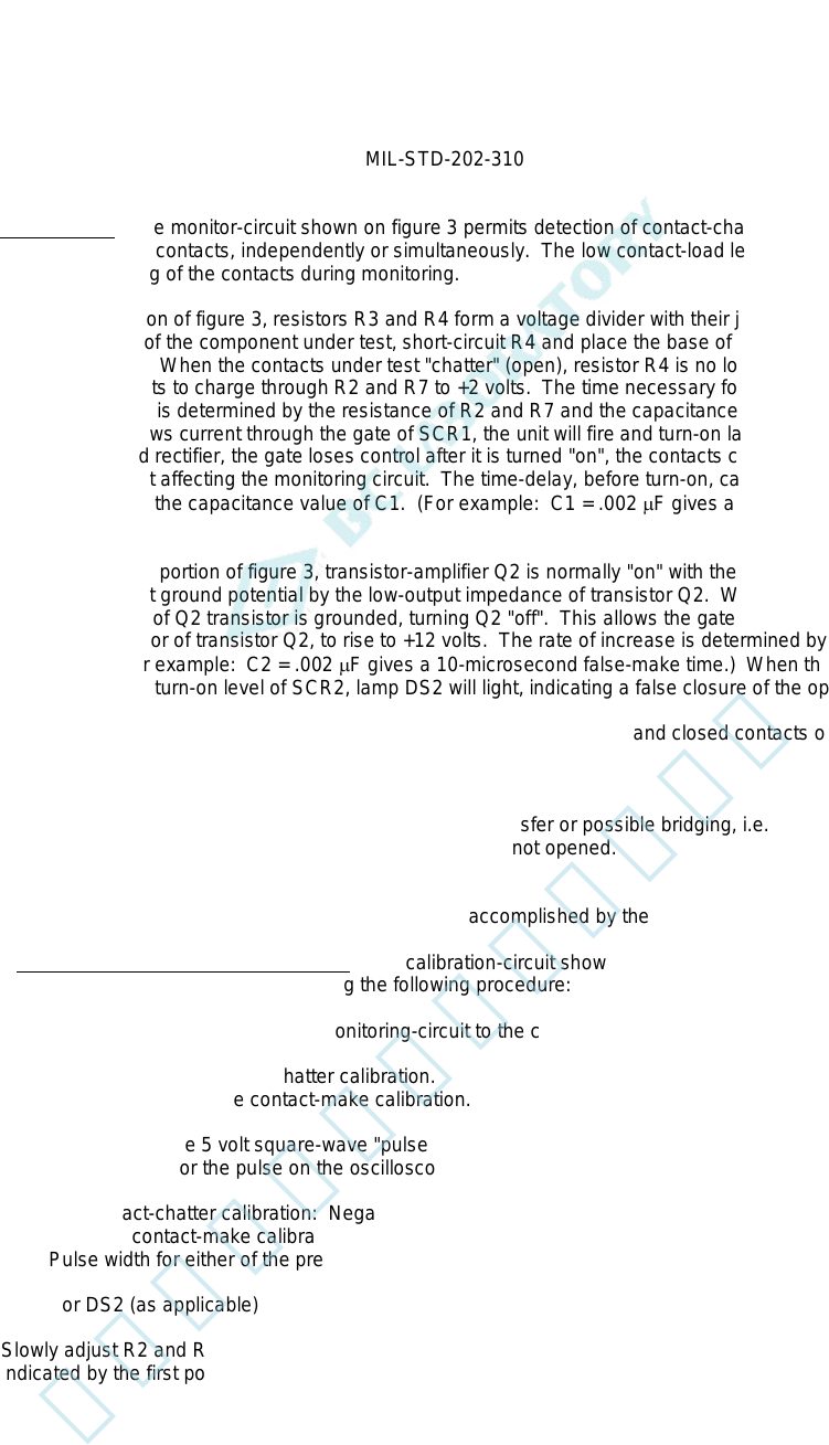
4.2.2 Test circuit B. The monitor-circuit shown on figure 3 permits detection of contact-chatter of closed contacts
and false closure of open contacts, independently or simultaneously. The low contact-load levels (see 4.1.1.2) insure
that there will be no arcing of the contacts during monitoring.
a. The chatter portion of figure 3, resistors R3 and R4 form a voltage divider with their junction at +2 volts. The
closed contacts of the component under test, short-circuit R4 and place the base of transistor amplifier Q1 to
ground potential. When the contacts under test "chatter" (open), resistor R4 is no longer short-circuited and
capacitor C1 starts to charge through R2 and R7 to +2 volts. The time necessary for C1 to charge to the
correct bias-level is determined by the resistance of R2 and R7 and the capacitance value of C1. As
transistor Q1 draws current through the gate of SCR1, the unit will fire and turn-on lamp DS1. Since in a
silicon-controlled rectifier, the gate loses control after it is turned "on", the contacts can reclose at any time
thereafter without affecting the monitoring circuit. The time-delay, before turn-on, can be adjusted by varying
R2 and selecting the capacitance value of C1. (For example: C1 = .002 µF gives a 10-microsecond open-
contact time.)
b. In the false-make portion of figure 3, transistor-amplifier Q2 is normally "on" with the gate of SCR2 being
effectively held at ground potential by the low-output impedance of transistor Q2. When a "false-make"
occurs, the base of Q2 transistor is grounded, turning Q2 "off". This allows the gate of the SCR2, which is
tied to the collector of transistor Q2, to rise to +12 volts. The rate of increase is determined by the value of
C2 and R8. (For example: C2 = .002 µF gives a 10-microsecond false-make time.) When the voltage
reaches the gate turn-on level of SCR2, lamp DS2 will light, indicating a false closure of the open contacts.
c. When this circuit is being used to simultaneously monitor both the open and closed contacts of a double set
of contacts:
(1) If DS1 "lights", it is an indication of contact chatter.
(2) If DS1 and DS2 "lights", it is an indication of false transfer or possible bridging, i.e., the movable contact
of the open circuit "closes" but the closed circuit has not opened.
(3) If DS2 "lights", it is an indication of bridging.
d. Restoration of the circuit for an indication of failure is accomplished by the operation of S1.
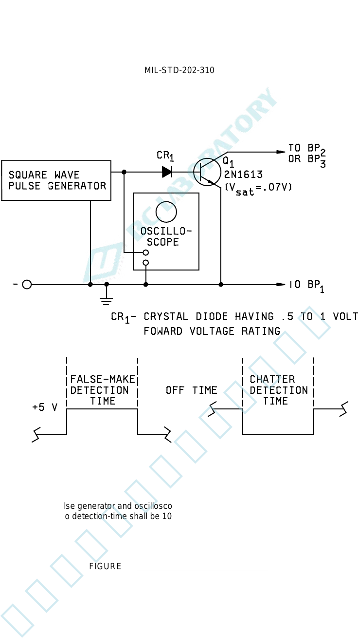
4.2.2.1 Calibration procedure for test-circuit B. The calibration-circuit shown on figure 4 may be used to calibrate
the monitoring-circuit shown on figure 3 by using the following procedure:
a. Make the proper connections of the monitoring-circuit to the calibration-circuit.
(1) BP1 and BP2 for contact-chatter calibration.
(2) BP1 and BP3 for false contact-make calibration.
b. Select the appropriate 5 volt square-wave "pulse-polarity" and "pulse-width" to be furnished by the pulse
generator and monitor the pulse on the oscilloscope, as follows:
(1) For contact-chatter calibration: Negative pulse.
(2) For false contact-make calibration: Positive pulse.
(3) Pulse width for either of the preceding (1) or (2) equal to the required detection time.
c. If DS1 or DS2 (as applicable) "lights", adjust R2 or R8 until the light is extinguished.
d. Slowly adjust R2 and R8 (as applicable) to the time-duration specified in the individual specification, as
indicated by the first point at which DS1 or DS2 "lights".
6
北测(上海)电子科技有限公司
联系方式:xuyj@beice-sh.com 13917165676
MIL-STD-202-310
NOTES:
1. The square-wave pulse generator and oscilloscope shall have an accuracy of ±3 percent or better.
2. The ratio of off-time to detection-time shall be 10:1 or better.
FIGURE 4. Calibration circuit for test-circuit B.
7
北测(上海)电子科技有限公司
联系方式:xuyj@beice-sh.com 13917165676
MIL-STD-202-310
4.3. Procedure.
4.3.1 Preparation. The monitor-circuits of figures 1 and 3 shall be calibrated, immediately prior to use, using the
applicable calibration-circuit (see figures 2 and 4, respectively). The calibration-circuit shall then be disconnected
from the monitoring-circuit.
4.3.2 Points of connection. The contacts of the test-specimen being monitored shall be connected to points BP1
and BP2 for test circuit A for both contact-chatter and false-make contact conditions. For test circuit B, the points of
connection shall be BP1 and BP2 for contact-chatter condition and to points BP1 and BP3 for false-make contact
condition. The test specimen shall then be subjected to the shock, vibration, acceleration, or other environmental test
during which this contact-chatter monitoring test method is to be used. If specified in the individual specification, test
specimens having normally-closed contacts may be wired in series to monitor for opening of contacts, and those
having normally-open contacts may be wired in parallel to monitor for closing of contacts. In this case, if contact
opening or closing is indicated, it will then be necessary to reset each test specimen separately and monitor it
individually to determine which one is defective.
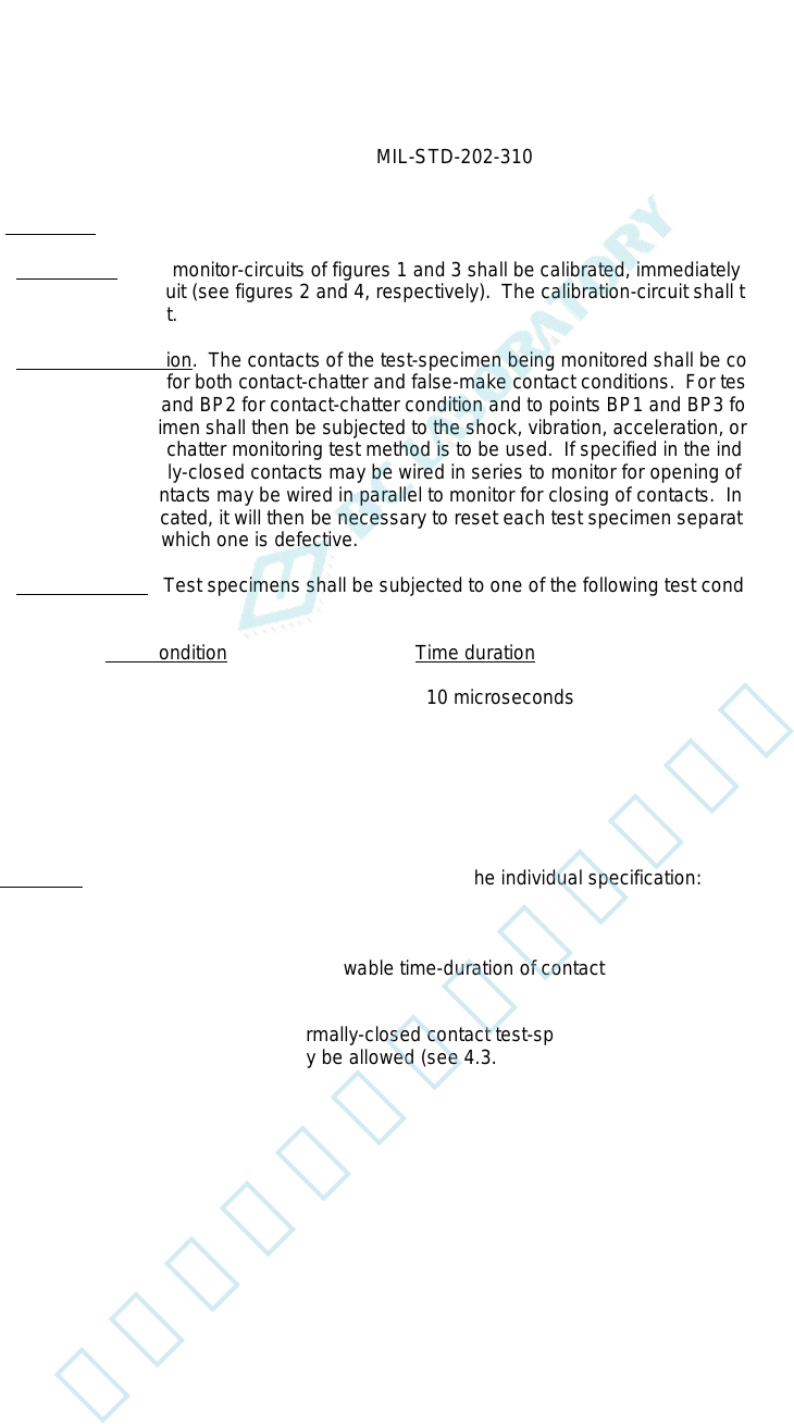
4.3.3 Test conditions. Test specimens shall be subjected to one of the following test conditions, as specified in the
individual specification:
Test condition Time duration
A 10 microseconds
B 100 microseconds
C 1 millisecond
D 5 milliseconds
E 20 milliseconds
5. DETAILED REQUIREMENTS
5.1 Summary. The following details are to be specified in the individual specification:
a. Test circuit letter (see 4.1.1, 4.2.1, and 4.2.2).
b. Test condition letter for maximum allowable time-duration of contact-opening or closing, as applicable (see
4.3.3).
c. Whether series-connection (of normally-closed contact test-specimens) or parallel-connection (of normally-
open contact test-specimens) may be allowed (see 4.3.2).
8
北测(上海)电子科技有限公司
联系方式:xuyj@beice-sh.com 13917165676