MIL-STD-202H.pdf - 第144页
MI L - S TD - 202 - 207 1/ Quan t i t i es ar e f or on e m ou ntin g. 2/ The s i z e of t he a ux i l i ar y m o unt ing plate sh all be increas ed to .50 x 36.00 x 34. 00 for panel s No. 5 and No. 6 listed i n t a bl e…
MIL-STD-202-207
Item
Description
Material
Quantity 1/
1
2
3
4
5
6
7
8
9
10
11
12
13
14
15
16
Panel
Standard channel, 3 x 5 pound
Fabricated spacer
Spacer stiffener
Fabricated spacer
Hex head bolt, .750-10UNC-2A x .75 lg
Hex head nut, .750-10UNC-2B
Washer, 2.00 OD x .18 ID
Washer, 1.38 OD x .18 ID
Hex head bolt, .500-13UNC-2A x 1.00 lg
Hex head nut, .500-13UNC-2B
Washer, 1.38 OD x .56 ID
Hex head bolt, .750-10UNC-2A x 4.00 lg
Spacer block
Strap, .12 x 1.00
Block, 2.25 x 21.25
Steel
Steel
Steel
Steel
Steel
Steel
Steel
Steel
Steel
Steel
Steel
Steel
Steel
Steel
Steel
Steel
1
2
1
4
1
8
12
12
12
4
4
4
4
4
4
4
1/ Quantities are for one mounting.
Inches mm Inches mm Inches mm Inches mm
.06 1.52 1.12 28.45 4.00 101.60 12.50 317.50
.12 3.05 1.31 33.27 4.50 114.30 13.00 330.20
.18 4.57 1.38 35.05 5.00 127.00 14.00 355.60
.25 6.35 1.50 38.10 7.00 177.80 15.00 381.00
.56 14.22 1.75 44.45 8.00 203.20 21.00 533.40
.62 15.75 2.00 50.80 9.00 228.60 21.25 539.75
.75 19.05 2.25 57.15 10.00 254.00 23.00 584.20
.81 20.57 3.00 76.20 10.50 266.70 25.00 635.00
1.00 25.40 3.50 88.90 11.50 292.10 28.00 710.20
30.00 762.00
34.00 863.60
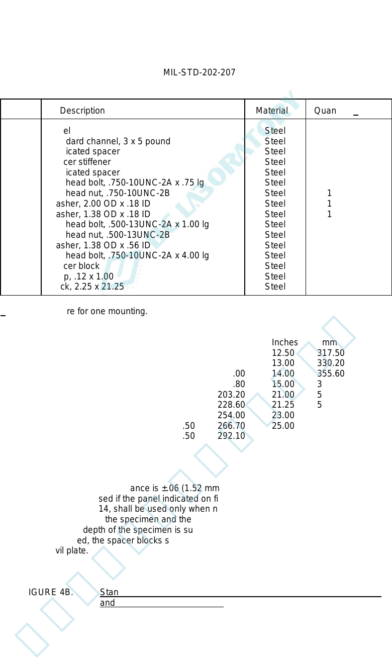
NOTES:
1. Unless otherwise specified, tolerance is ±.06 (1.52 mm).
2. This panel shall not be used if the panel indicated on figure 4A is applicable.
3. The spacer blocks, item 14, shall be used only when necessary to maintain a minimum clearance of 1.00
inch (25.40 mm) between the specimen and the anvil plate.
4. In the event that the depth of the specimen is such that the minimum clearance of 1.00 inch (25.40 mm)
cannot be maintained, the spacer blocks shall be removed and the specimen mounted with the front surface
toward the anvil plate.
FIGURE 4B. Standard mounting fixtures for electrical-indicating switchboard meters
and other panel-mounted parts - Continued.
11
北测(上海)电子科技有限公司
联系方式:xuyj@beice-sh.com 13917165676
MIL-STD-202-207
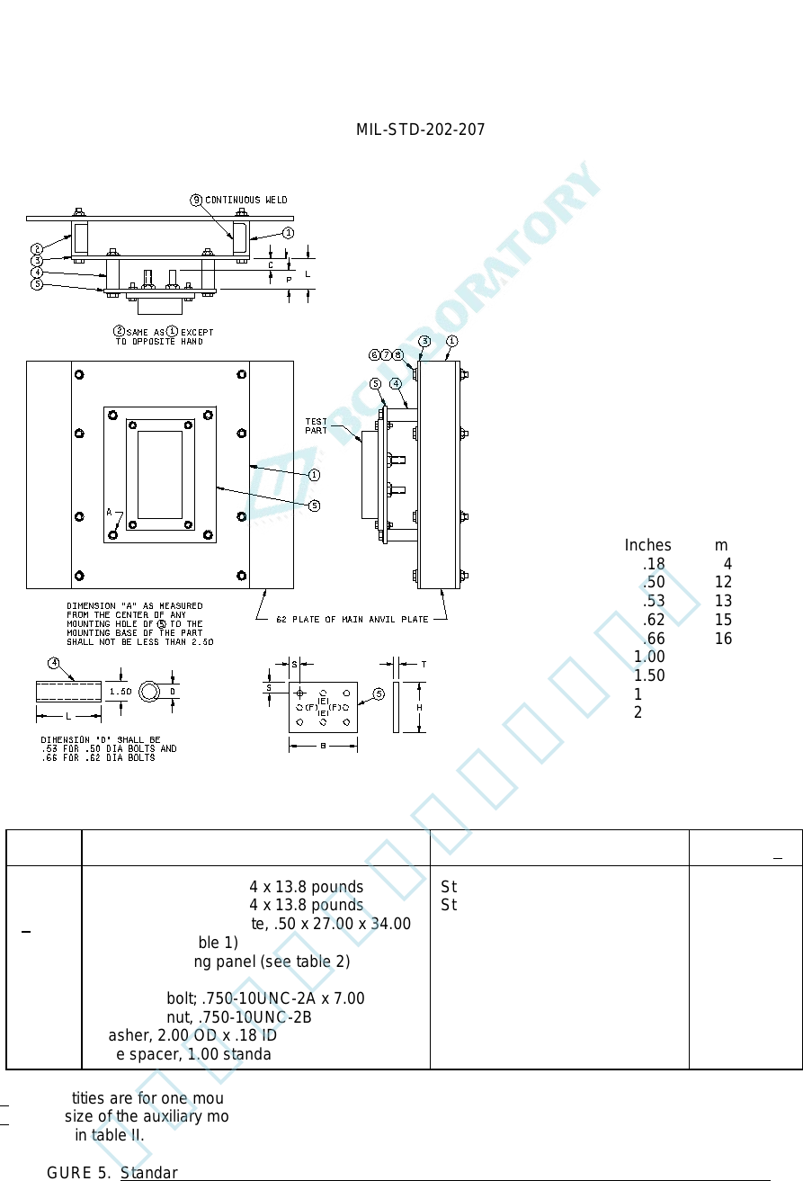
1/ Quantities are for one mounting.
2/ The size of the auxiliary mounting plate shall be increased to .50 x 36.00 x 34.00 for panels No. 5 and No. 6
listed in table II.
FIGURE 5. Standard mounting fixtures for electrical controller parts (contractors, relays, resistors, etc.).
Inches mm
.18 4.57
.50 12.70
.53 13.46
.62 15.75
.66 16.76
1.00 25.40
1.50 38.10
1.94 49.28
2.00 50.80
2.50 63.50
7.00 177.80
27.00 685.80
34.00 863.60
36.00 914.40
Item
Description
Material
Quantity 1/
1
2
2/ 3
4
5
6
7
8
9
Car building channel, 4 x 13.8 pounds
Car building channel, 4 x 13.8 pounds
Auxiliary mounting plate, .50 x 27.00 x 34.00
Spacer (see table 1)
Plastic mounting panel (see table 2)
Hex head bolt; .750-10UNC-2A x 7.00 lg
Hex head nut, .750-10UNC-2B
Washer, 2.00 OD x .18 ID
Pipe spacer, 1.00 standard, 1.94 lg
Steel
Steel
Steel
Steel
Plastic, laminated, type FBG, in
accordance with MIL-I-24768/14
Steel (heat-treated)
Steel
Steel
Steel
1
1
1
8
8
16
8
12
北测(上海)电子科技有限公司
联系方式:xuyj@beice-sh.com 13917165676
MIL-STD-202-207
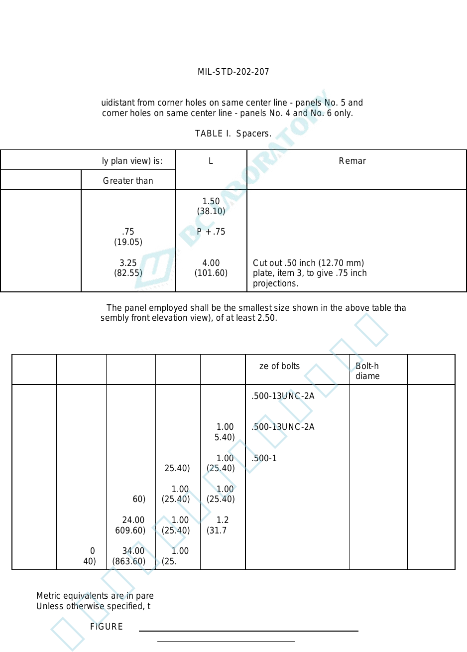
Holes (E) are drilled equidistant from corner holes on same center line - panels No. 5 and No. 6 only. Holes (F) are
drilled equidistant from corner holes on same center line - panels No. 4 and No. 6 only.
TABLE I. Spacers.
When P (note assembly plan view) is:
L
Remarks
Less than
Greater than
.75
(19.05)
3.25
(82.55)
.75
(19.05)
3.25
(82.55)
1.50
(38.10)
P + .75
4.00
(101.60)
Cut out .50 inch (12.70 mm) thick auxiliary mounting
plate, item 3, to give .75 inch clearance around rear
projections.
Selection of panel size: The panel employed shall be the smallest size shown in the above table that will result in a
clearance, "A" (note assembly front elevation view), of at least 2.50.
TABLE II. Mounting panels.
Panel
number
B
H
T
S
Size of bolts
Bolt-hole
diameter
Quantity
1
2
3
4
5
6
9.00
(228.60)
12.00
(304.80)
16.00
(406.40)
20.00
(508.00)
32.00
(812.80)
36.00
(914.40)
12.00
(304.80)
16.00
(406.40)
20.00
(508.00)
24.00
(609.60)
24.00
(609.60)
34.00
(863.60)
.75
(19.05)
1.00
(25.40)
1.00
(25.40)
1.00
(25.40)
1.00
(25.40)
1.00
(25.40)
1.00
(25.40)
1.00
(25.40)
1.00
(25.40)
1.00
(25.40)
1.25
(31.75)
1.25
(31.75)
.500-13UNC-2A
.500-13UNC-2A
.500-13UNC-2A
.500-13UNC-2A
.625-11UNC-2A
.625-11UNC-2A
.56
(14.22)
.56
(14.22)
.56
(14.22)
.56
(14.22)
.69
(17.53)
.69
(17.53)
4
4
4
6
6
8
NOTES:
1. Metric equivalents are in parentheses.
2. Unless otherwise specified, tolerances are ±.06 inch (1.52 mm).
FIGURE 5. Standard mounting fixtures for electrical controller parts
(contractors, relays, resistors, etc.) - Continued.
13
北测(上海)电子科技有限公司
联系方式:xuyj@beice-sh.com 13917165676