MIL-STD-202H.pdf - 第39页
MI L - S TD - 202 - 10 6 4.2. Procedure. 4.2.1 Mount ing . Spec i m ens s hal l be m ou nt ed by t hei r nor m al m ount i ng m ea ns , i n t hei r no rmal mou nting po sit ion, but shall be positione d so t ha t t hey d…
MIL-STD-202-106
METHOD 106
MOISTURE RESISTANCE
1. SCOPE
1.1 Purpose. The moisture resistance test is performed for the purpose of evaluating, in an accelerated manner,
the resistance of component parts and constituent materials to the deteriorative effects of the high-humidity and heat
conditions typical of tropical environments. Most tropical degradation results directly or indirectly from absorption of
moisture vapor and films by vulnerable insulating materials, and from surface wetting of metals and insulation. These
phenomena produce many types of deterioration, including corrosion of metals, physical distortion and decomposition
of organic materials, leaching out and spending of constituents of materials; and detrimental changes in electrical
properties. This test differs from the steady-state humidity test (method 103 of this standard) and derives its added
effectiveness in its employment of temperature cycling, which provides alternate periods of condensation and drying
essential to the development of the corrosion processes and, in addition, produces a "breathing" action of moisture
into partially sealed containers. Increased effectiveness is also obtained by use of a higher temperature, which
intensifies the effects of humidity. The test includes low temperature and vibration subcycles (when applicable, see
4.2.4.2) that act as accelerants to reveal otherwise indiscernible evidence of deterioration since stresses caused by
freezing moisture and accentuated by vibration tend to widen cracks and fissures. As a result, the deterioration can
be detected by the measurement of electrical characteristics (including such tests as dielectric withstanding voltage
and insulation resistance) or by performance of a test for sealing. Provision is made for the application of a polarizing
voltage across insulation to investigate the possibility of electrolysis, which can promote eventual dielectric
breakdown. This test also provides for electrical loading of certain components, if desired, in order to determine the
resistance of current-carrying components, especially fine wires and contacts, to electro-chemical corrosion. Results
obtained with this test are reproducible and have been confirmed by investigations of field failures. This test has
proven reliable for indicating those parts which are unsuited for tropical field use.
2. APPLICABLE DOCUMENTS
This section not applicable to this standard.
3. DEFINTIONS
This section not applicable to this standard.
4. GENERAL REQUIREMENTS
4.1 Apparatus
4.1.1 Chamber. A test chamber shall be used which can meet the temperature and humidity cycling specified on
figure 1. The material used to fabricate the platforms and standoffs, which support the specimens, shall be non-
reactive in high humidity. Wood or plywood shall not be used because they are resiniferous. Materials shall not be
used if they contain formaldehyde or phenol in their composition. Provisions shall be made to prevent condensate
from the chamber ceiling dripping onto the test specimens.
4.1.1.1 Opening of the chamber door. During the periods when the humidity is ascending or descending, the
chamber door should not be opened. If the chamber door must be opened, it should be opened during the 16th hour
through the 24th hour of an individual cycle. While the chamber is at 25°C (77°F), and the relative humidity tolerance
must be maintained, the chamber door should be opened only for a short period of time.
4.1.1.2 Water. Steam, or distilled and demineralized, or deionized water, having a pH value between 6.0 and 7.2
at 23°C (73.4°F) shall be used to obtain the specified humidity. No rust or corrosive contaminants shall be imposed
on the test specimens by the test facility.
1
北测(上海)电子科技有限公司
联系方式:xuyj@beice-sh.com 13917165676
MIL-STD-202-106
4.2. Procedure.
4.2.1 Mounting. Specimens shall be mounted by their normal mounting means, in their normal mounting position,
but shall be positioned so that they do not contact each other, and so that each specimen receives essentially the
same degree of humidity.
4.2.2 Initial measurements. Prior to step 1 of the first cycle, the specified initial measurements shall be made at
room ambient conditions, or as specified.
NOTES:
1. Allowance of 100 percent RH is intended to avoid problems in reading values close to 100 percent RH, but
actual chamber operation shall be such so as to avoid condensation.
2. Unless otherwise specified, the steady state temperature tolerance is ±2°C at all points within the immediate
vicinity of the specimens and the chamber surfaces.
3. Rate of change of temperature is unspecified; however, specimens shall not be subjected to radiant heat from
chamber-conditioning processes.
4. Circulation of air in the chamber shall be at a minimum cubic rate per minute equivalent to 5 times the volume
of the chamber.
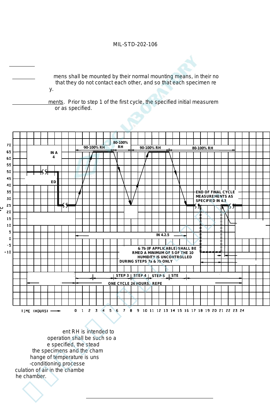
FIGURE 1. Graphical representation of moisture-resistance test.
INITIAL CON-
DITIONING IN A
DRY OVEN 24
HOURS
HUMIDITY
UNCONTROLLED
INITIAL MEASRUEMENTS
AS SPECIFIED IN 4.2.2
END OF FINAL CYCLE
MEASUREMENTS AS
SPECIFIED IN 4.3
VIBRATE IS 15
MINUTES AS
SPECIFIED IN
4.2.4.2
90-100% RH
90
-
100% RH
80
-
100% RH
80-100%
RH
+10°C
-2°C
VOLTAGE APPLIED AS SPECIFIED IN 4.2.5
STEPS 7a & 7b (IF APPLICABLE) SHALL BE
PERFORMED A MINIMUM OF 5 OF THE 10
CYCLES. HUMIDITY IS UNCONTROLLED
DURING STEPS 7a & 7b ONLY
STEP 7b
STEP 7a
PRIOR TO FIRST CYCLE
UNLESS OTHERWISE
SPECIFIED
STEP 1 STEP 2
STEP 3
STEP 4
STEP 5
STEP 6 STEP 7
ONE CYCLE 24 HOURS. REPEAT AS SPECIFIED IN 4.2.3
2
北测(上海)电子科技有限公司
联系方式:xuyj@beice-sh.com 13917165676
MIL-STD-202-106
4.2.3 Number of cycles. Specimens shall be subjected to 10 continuous cycles, each as shown on figure 1. In the
event of no more than one unintentional test interruption (power interruption or equipment failure) prior to the
completion of the specified number of cycles (except for the last cycle), the cycle shall be repeated and the test may
continue. Unintentional interruptions occurring during the last cycle require a repeat of the cycle plus an additional
uninterrupted cycle. Any intentional interruption, or any unintentional interruption of greater than 24 hours requires a
complete retest.
4.2.4 Subcycle of step 7. During at least 5 of the 10 cycles, a low temperature subcycle and, if applicable, a
vibration subcycle shall be performed.
4.2.4.1 Step 7a. At least 1 hour but not more than 4 hours after step 7 begins, the specimens shall be either
removed from the humidity chamber, or the temperature of the chamber shall be reduced. Specimens shall then be
conditioned at -10°C ±2°C (14°F ±3.6°F) with humidity not controlled, for 3 hours minimum as indicated on figure 1.
When a separate cold chamber is not used, care should be taken to assure that the specimens are held at
-10°C ±2°C (14°F ±3.6°F) for the full 3 hour period. (If step 7b is not applicable, the specimens shall be returned to
25°C (77°F) at 80 percent relative humidity minimum and kept there until the next cycle begins.)
4.2.4.2 Step 7b (when applicable). Within 15 minutes after completion of step 7a and with humidity not controlled
and temperature at room ambient, specimens shall be vibrated for 15 minutes, using a simple harmonic motion having
an amplitude of 0.03 inch (0.76 mm), (0.06 inch (1.52 mm) maximum total excursion), the frequency being varied
uniformly between the approximate limits of 10 and 55 hertz (Hz). The entire frequency range, from 10 to 55 Hz and
return to 10 Hz, shall be traversed in approximately 1 minute. After step 7b, the specimens shall be returned to 25°C
(77°F) at 80 percent relative humidity minimum and kept there until the next cycle begins.
NOTE: Step 7b is not applicable to parts that include test schedules with vibration requirements (such as method
201 or method 204 of this standard). These parts must routinely be subjected to, and pass, these requirements.
NOTE: Allowance of 100 percent RH is intended to avoid problems in reading values close to 100 percent, but
actual chamber operation shall be such so as to avoid condensation.
4.2.5 Polarization and load. When applicable, polarization voltage shall be 100 volts dc, or as specified. The
loading voltage shall be as specified.
4.3 Final measurements.
4.3.1 At high humidity. Upon completion of step 6 of the final cycle (or step 7 if the subcycle of 4.2.4 is performed
during the tenth cycle), when measurements at high humidity are specified, the specimens shall be maintained at a
temperature of 25°C ±2°C (77°F ±3.6°F), and a RH of 80 percent minimum for a period of 1½ to 3½ hours, after
which the specified measurements shall be made. Due to the difficulty in making measurements under high humidity
conditions, the individual specification shall specify the particular precautions to be followed in making measurements
under such conditions.
(NOTE: Allowance of 100 percent RH is intended to avoid problems in reading values close to 100 percent, but
actual chamber operation shall be such so as to avoid condensation.)
4.3.2 After high humidity. Upon removal from humidity chamber, final measurements shall be made within a
period of 1 to 2 hours after the final cycle. During final measurements, specimens shall not be subjected to any
means of artificial drying.
4.3.3 After drying period. Following step 6 of the final cycle (or step 7 if the subcycle of 4.2.4 is performed during
the tenth cycle), or following measurements at high humidity, if applicable, specimens shall be conditioned for 24
hours at the ambient conditions specified for the initial measurements (see 4.2.2) after which the specified
measurements shall be made. Measurements may be made during the 24 hour conditioning period; however, any
failures which occur shall be considered as failures and shall not be retested later for the purpose of obtaining an
acceptable result.
3
北测(上海)电子科技有限公司
联系方式:xuyj@beice-sh.com 13917165676