MIL-STD-202H.pdf - 第73页
MI L - S TD - 202 -1 1 1 M E TH O D 1 1 1 F L AM M ABI L I T Y (E XT ER N AL F L AM E) 1. SCOPE 1. 1 P urpose . T his test i s per f or m ed f or t he p ur po s e o f de t er m i ni ng t he f l am m ab i l i t y of a p a…
MIL-STD-202-111
CONTENTS
PARAGRAPH PAGE
FOREWORD…………………………………………………………. ii
1. SCOPE 1
1.1 Purpose………………………………………….……..…………. 1
2. APPLICABLE DOCUMENTS 1
3. DEFINTIONS 1
4. GENERAL REQUIREMENTS 1
4.1 Apparatus ……………………………………………..…………. 1
4.1.1 Test chamber…………………………………………………….. 1
4.1.2 Mounting apparatus.…………………………………………….. 1
4.1.3 Propane torch.……..…………………………….………………. 1
4.1.4 Timing device…………………………………………………….. 1
4.2 Procedure…………………………………………………………. 1
4.3 Cleaning………………………………………………………….. 2
4.4 Measurements………..………………………………………….. 2
5. DETAILED REQUIREMENTS 2
5.1 Summary……………..…………………………..………………. 2
6. NOTES 5
6.1 Supersession data………………………………………………. 5
FIGURE PAGE
1. Burner head……………………………………………………………..….. 2
iii
北测(上海)电子科技有限公司
联系方式:xuyj@beice-sh.com 13917165676
MIL-STD-202-111
METHOD 111
FLAMMABILITY (EXTERNAL FLAME)
1. SCOPE
1.1 Purpose. This test is performed for the purpose of determining the flammability of a part exposed to an
external flame. Flammability is defined as the ability of a part to support combustion. This can be determined by the
following: the time it takes for a part to become self-extinguishing after application of a flame; that the part does not
support violent burning; that exposure of a part to a flame does not result in an explosive-type fire; or that spreading
of surface burning on larger parts is deterred. The principal factors which affect the results of an external flame test
are -- the heat of the flame at the point of impingement; the size of the flame; the time of exposure to the flame; the
volume of the part and other heat-sink effects; the presence of circulating materials and surfaces of the parts.
2. APPLICABLE DOCUMENTS
This section not applicable to this standard.
3. DEFINTIONS
This section not applicable to this standard.
4. GENERAL REQUIREMENTS
4.1. Apparatus.
4.1.1 Test chamber. An enclosure protected from air currents, but provided with means for venting fumes and
admitting an adequate supply of fresh air at the bottom, shall be used. A standard chemistry hood with the exhaust
fan turned off, or a metal box about 2 feet wide by 3 feet high and 2 feet deep, with a removable front, a viewing
window, and holes for air intake and venting of fumes, is satisfactory. Adequate safety precautions should be taken
to protect personnel from possible explosion of the test specimens.
4.1.2 Mounting apparatus. Within the test chamber, a support stand with suitable adjustable vertical brackets or
other mounting clamps shall be used to hold the specimens at the specified distance and position (see 4.2) with
respect to the applied flame. Mounting clamps, in order not to act as heat sinks, shall be thermally insulated from the
specimens. The flame shall not impinge on the clamp(s) or other devices which hold the specimens.
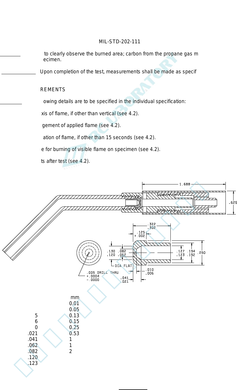
4.1.3 Propane torch. A propane torch, having a nozzle assembly conforming to Model TX-1 of "Bernzomatic
Corporation", or equal, shall be the source of the flame. "Cracked" propane gas shall be used as the fuel. A
suggested torch assembly is shown on figure 1, Burner head.
4.1.4 Timing device. A timing device, which can indicate time in seconds, shall be used to determine the time of
application of the flame and the time of burning of visible flame on the specimen.
4.2. Procedure. The specimen shall be mounted in the test chamber (see 4.1.1) with the mounting apparatus
therein (see 4.1.2) and at the distance and position specified. The torch shall be placed so that the axis of the flame
is in the vertical direction, unless otherwise specified in the individual specification. When the torch is ignited, and
after the flame is stable, the flow of gas through the nozzle of the torch (see 4.1.3) shall be adjusted so that the inner-
cone length is 1/2 inch between the inner-cone tip and a point in the plane of the nozzle rim. The specimen shall be
placed so that the point of impingement of the flame on the specimen is 1-1/2 inches from the nozzle rim along the
flame axis. The point of impingement of the flame shall be as specified in the individual specification. The flame shall
be applied to the specimen for a period of 15 seconds unless specified in the individual specification, as determined
by the timing device (see 4.1.4), and then removed. Upon removal of the applied flame, the time of burning of visible
flame on the specimen, as determined by the timing device, shall be recorded. The recorded time shall then be
compared with the allowable time specified in the individual specification. Any violent burning of the specimen or
explosive-type fire shall be recorded.
1
北测(上海)电子科技有限公司
联系方式:xuyj@beice-sh.com 13917165676
MIL-STD-202-111
4.3 Cleaning. In order to clearly observe the burned area; carbon from the propane gas may be removed by
brushing or buffing the specimen.
4.4. Measurements. Upon completion of the test, measurements shall be made as specified in the individual
specification.
5. DETAILED REQUIREMENTS
5.1 Summary. The following details are to be specified in the individual specification:
a. Direction of axis of flame, if other than vertical (see 4.2).
b. Point of impingement of applied flame (see 4.2).
c. Time of application of flame, if other than 15 seconds (see 4.2).
d. Allowable time for burning of visible flame on specimen (see 4.2).
e. Measurements after test (see 4.2).
Inches mm Inches mm
.0004 0.01 .125 3.18
.002 0.05 .127 3.23
.005 0.13 .130 3.30
.006 0.15 .192 4.88
.010 0.25 .194 4.93
.021 0.53 .250 6.35
.041 1.04 .302 7.67
.062 1.57 .322 8.18
.082 2.08 .625 15.88
.120 3.05 1.688 42.88
.123 3.12
MATERIAL: BRASS
FIGURE 1. Burner head.
2
北测(上海)电子科技有限公司
联系方式:xuyj@beice-sh.com 13917165676