FCM_User Reference Manual.pdf.pdf - 第140页
MIS User Re ference Manual 4022 5 91 96082 5-48 F CM Mult ifl ex 02.02 ✱✱ Detailed Infor mation When ba d pla c em en t s have been fou nd on vis ual boar d in spec tion, it is quite tim e consuming t o tr ace the ba dly…
4022 591 96082 User Reference Manual
02.02 FCM Multiflex 5-47
MIS
5.3.4 Troubleshooting
5.3.4.1 [Troubleshooting] > [Trace component...]
TABLE 5-22 Quick Reference
fcm0545a.tif
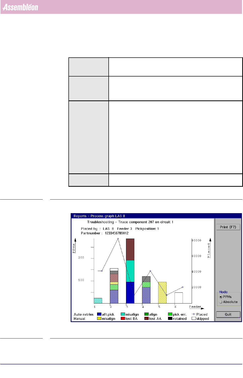
SCREEN 5-36 [Trace component...] process graph screen example
Actions ■ select [Functions...] in the MIS pull-down menu
■ select [Troubleshooting]
■ select [Trace component...]
Conditions ■ order active
■ item code of the badly placed SMDs must be known
■ in case of a multi-circuit board, the number of the board circuit on
which the problem exists must be known
Information following information will be given on the error environment:
■ the relevant placement module number
■ the relevant feeder position
■ the relevant pick position
■ the SMD reel’s partnumber used for the concerned SMDs
■ the number of auto retries
■ the number of manual retries
■ the number of placed SMDs
■ the number of not placed SMDs (skipped)
the occurred process errors on the traced SMD will be displayed in
bright colours, whereas the other errors are displayed in pale colours
Display Options ■ absolute error numbers
■ errors in Parts Per Millions (PPMs)
MIS
User Reference Manual 4022 591 96082
5-48 FCM Multiflex 02.02
✱✱Detailed Information
When bad placements have been found on visual board inspection, it is quite time
consuming to trace the badly placed SMDs back to the placement module(s) and
feeder(s) from which they originated. Especially if a lot of SMDs have been placed
on a board, and you need to search through the complete action spec.
By means of the SMD’s item code and the circuit number (as both used in the
action spec), the
[Trace component...] function gives you the possibility to easily
trace the errors back to the machine parts involved.
▼Displayed Information
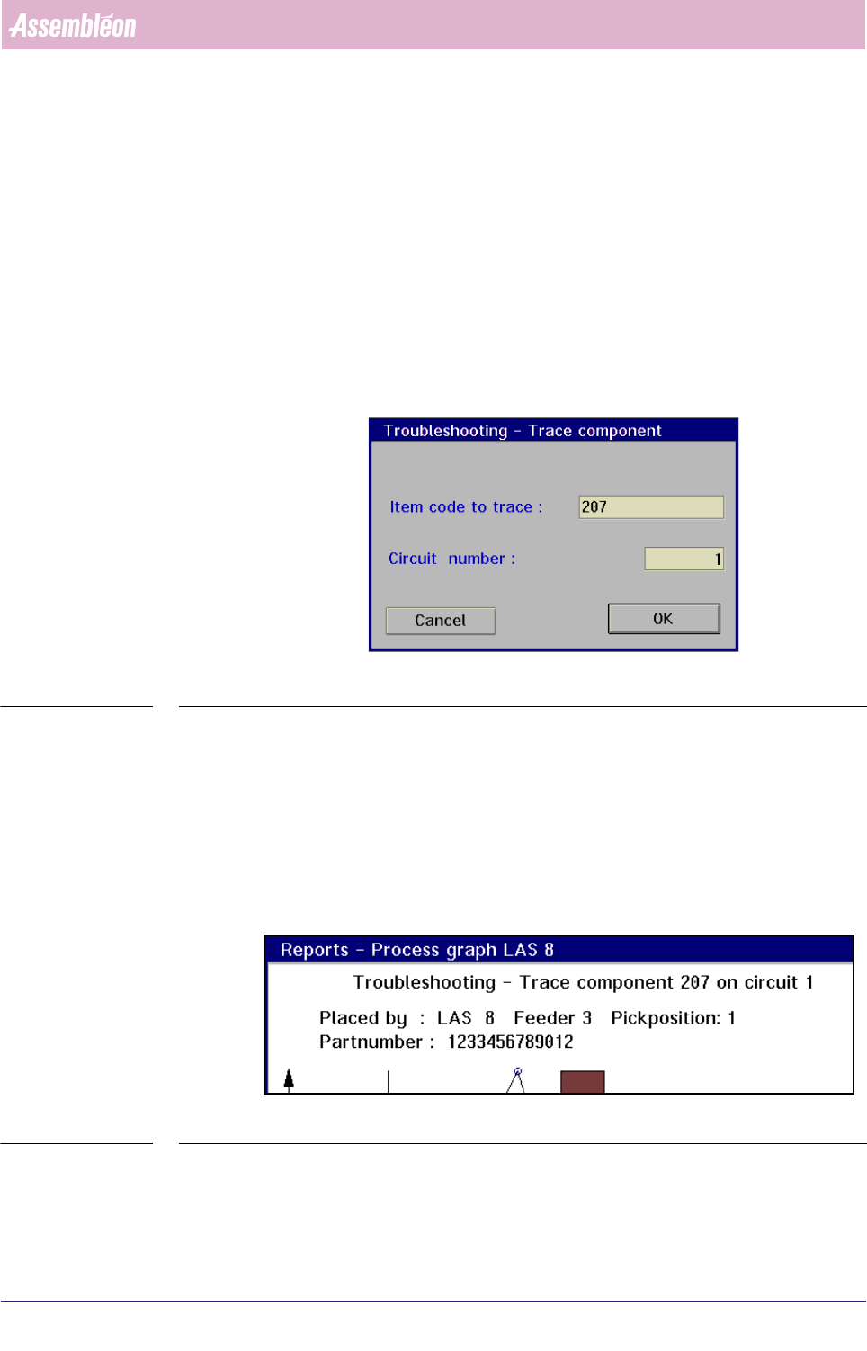
On selecting the [Trace component...] command, the following dialogue screen will
appear:
fcm0546a.tif
SCREEN 5-37
Once the item code and circuit number have been entered, the MIS system will
start searching for the SMD in the action spec.
If the entered SMD parameters are found, the process graph of the placement
module where this SMD is used will be displayed (see SCREEN 5-41).
■ On top of the graph, first the input information is shown:
• the component (SMD) number to be traced
• the concerned circuit number
fcm0547a.tif
SCREEN 5-38
■ Next, the output information is given:
• the placement module, the feeder, and the pick position where the
selected SMD type has been processed
4022 591 96082 User Reference Manual
02.02 FCM Multiflex 5-49
MIS
• the partnumber of the SMD reel that has been used for the selected SMD type
■ Below these informations, the process errors are displayed in bar-graphs, that
have different colours for each process error type. The amount of errors can be
read from the left Y-axis. This can either be in absolute numbers or in PPMs,
depending on the selected mode.
■ The number of placed SMDs are displayed in a line-graph. The amount of
placed SMDs can be read from the right Y-axis.
NOTE: The process errors that occurred on the traced SMD are displayed in bright
colours, the process errors for the other SMDs are displayed in pale colours.
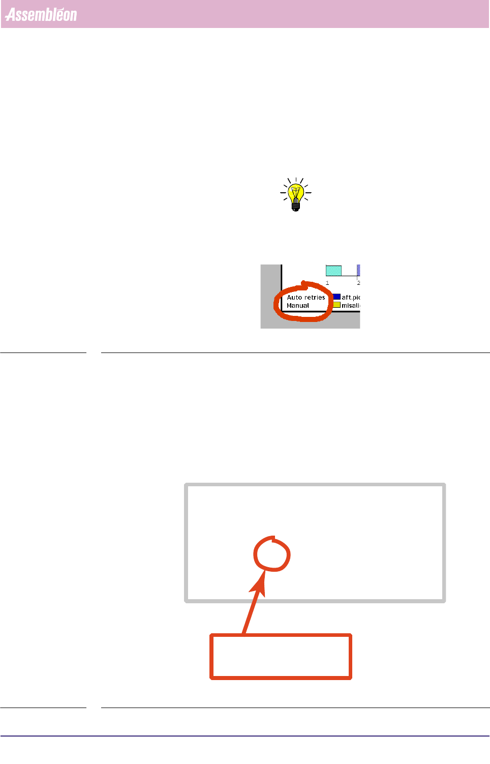
■ The process errors are divided into auto retries and manual retries (see below).
fcm0548a.tif
SCREEN 5-39
• An auto retry is a retry without operator intervention (automatic); the
maximum allowed number of auto retries is determined in the action spec,
(see SCREEN 5-16).
• A manual retry is a retry by operator intervention. After the FCM Multiflex
has reached the auto retry number limit, it stops, and manual retries may be
done by the operator then. Note that only those manual retries are taken
into account for the process report that were successful at first attempt.
fcm0549a.eps
SCREEN 5-40 Action spec setting of the maximum number of auto pick retries (refires)
FEEDER 1 1 T8-M/4 T 333-222-112 SOD-80
COMMENT index coordinates are relative to pipette origin
COMMENT indx/brd /refholex/refholey/board_x /board_y
INDEX 1 3 -75.500 294.250 -81.500 138.000
INDEX 1 4 74.500 294.250 68.500 138.000
INDEX 2 3 4.500 294.250 -1.500 138.000
COMMENT pick coordinates are relative to pipette origin
COMMENT fd/pk/psh/rfr/pick_x /pick_y /pick_phi/na/prf/arf/ale/ple
PICK 1 1 1 2 19.000 77.000 90.0 1 75 55 80 80
COMMENT: In case a deviating dump position is needed enter
COMMENT: DUMP position_x position_y
COMMENT mount coordinates are in board coordinates
in this example, the number of auto(matic)
pick retries (or
refires
) is set to 2
rfr = refires