FCM_User Reference Manual.pdf.pdf - 第150页
MIS User Re ference Manual 4022 5 91 96082 5-58 F CM Mult ifl ex 02.02 G rap h e xpl an at ion T ABLE 5- 27 fcm0 55a.tif SCREE N 5-48 Example of a [Servo d i agnostic ...] gra ph in [T rac kin g] mo de Graph legend Expla…
4022 591 96082 User Reference Manual
02.02 FCM Multiflex 5-57
MIS
5.3.5.2 [Reports] > [Servo diagnostic...]
TABLE 5-26 Quick Reference
fcm0555a.tif
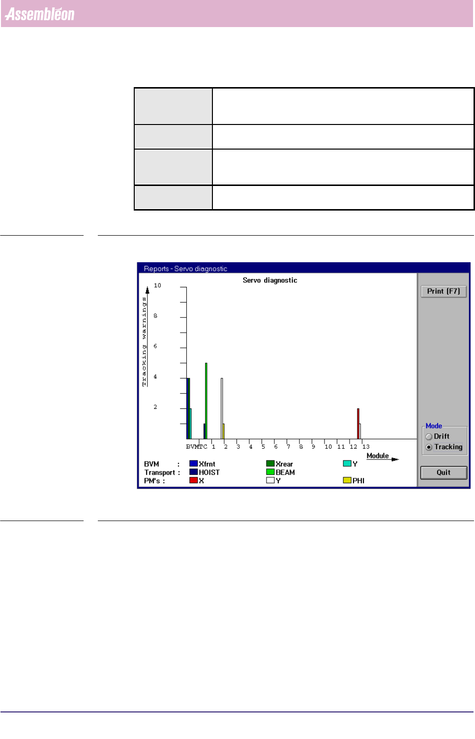
SCREEN 5-47 Example of a [Servo diagnostic...] graph in [Tracking] mode
✱✱Detailed Information
▼Displayed Information
The [Servo diagnostic...] graph gives a graphical overview of all tracking warnings
and drift that occurred on the various FCM Multiflex modules.
A tracking warning is generated when the difference between aimed and achieved
motion (“slip”) of the servo system exceeded a fixed limit.
The drift is defined as the total number of servo increment pulses that did not
match the nominal value.
Actions ■ select [Functions...] in the MIS pull-down menu
■ select [Reports]
■ select [Machine performance...]
Conditions ■ supervisor access level
■ order active
Information ■ information on all servo systems by graphical display of
• the total number of tracking warnings per servo system
• the total drift that occurred per servo system
Display Options ■ display of tracking warnings
■ display of drift
MIS
User Reference Manual 4022 591 96082
5-58 FCM Multiflex 02.02
Graph explanation
TABLE 5-27
fcm055a.tif
SCREEN 5-48 Example of a [Servo diagnostic...] graph in [Tracking] mode
Graph legend Explanation
Tracking warnings scale for the total number of tracking warnings,
which can be defined as:
the number of times the difference between aimed
and achieved motion (“slip”) of the servo system
exceeded a fixed (warning) limit (in Tracking mode
only)
Module along this line the various used modules involved
are indicated
BVM Xfrnt the number of times a tracking warning occurred for
the BVM’s X-motor at the front side
Xrear the number of times a tracking warning occurred for
the BVM’s X-motor at the rear side
Y the number of times a tracking warning occurred for
the BVM’s Y-motor
Transport HOIST the number of times a tracking warning occurred for
the hoist motor of the transport beam
BEAM the number of times a tracking warning occurred for
the X-motor of the transport beam
PMs X the number of times a tracking warning occurred for
the X-motor of the indicated placement module
Y the number of times a tracking warning occurred for
the Y-motor of the indicated placement
module
PHI the number of times a tracking warning occurred for
the PHI-motor of the indicated placement
module
4022 591 96082 User Reference Manual
02.02 FCM Multiflex 5-59
MIS
TABLE 5-28
fcm0556a.tif
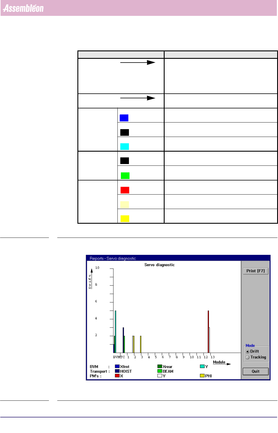
SCREEN 5-49 Example of a [Servo diagnostic...] graph in [Drift] mode
Graph legend Explanation
Drift scale for the total amount of drift, which can be
defined as:
the total number of servo increment pulses that did
not match the nominal value (in Drift mode only)
Module Module along this line the various used modules
involved are indicated
BVM Xfrnt the total amount of drift that occurred for the BVM’s
front side X-motor
Xrear the total amount of drift that occurred for the BVM’s
rear side X-motor
Y the total amount of drift that occurred for the BVM’s
Y-motor
Transport HOIST the total amount of drift that occurred for the hoist
motor of the transport beam
BEAM the number of times a tracking warning occurred for
the X-motor of the transport beam
PMs X the total amount of drift that occurred for the X-
motor of the indicated placement module
Y the total amount of drift that occurred for the Y-
motor of the indicated placement module
PHI the total amount of drift that occurred for the PHI-
motor of the indicated placement module