FCM_User Reference Manual.pdf.pdf - 第261页
4022 591 960 82 Us er Reference Man ual 02.02 FC M Multif lex 6-69 Pr oduc t Ch ang e Ov er NOTE: CHIP SMD info files only con tain vision processing parameters. In the vision processing param eters , the concept o f a r…
Product Change Over
User Reference Manual 4022 591 96082
6-68 FCM Multiflex 02.02
▼ LEAD_LENGTH
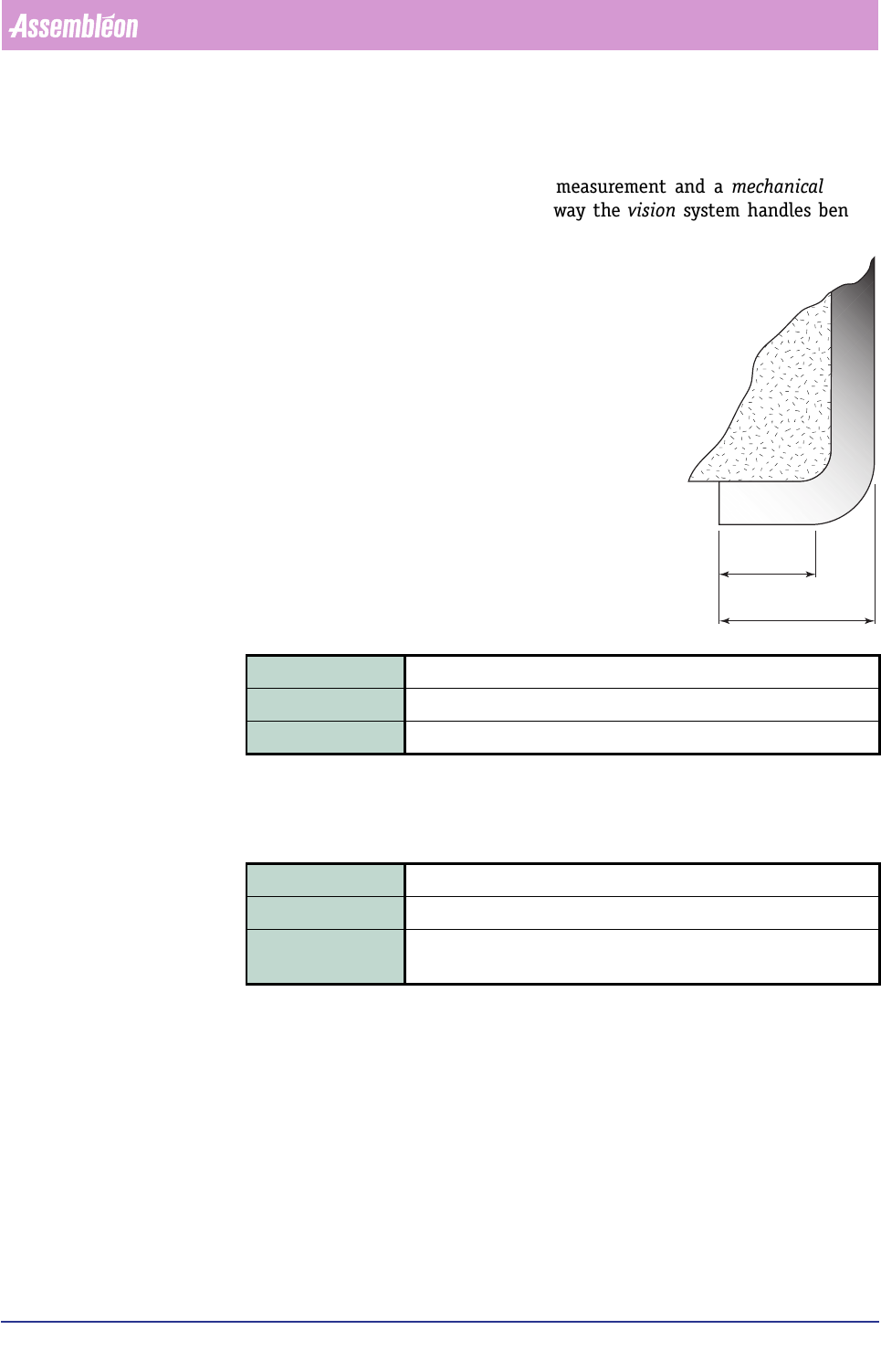
This parameter defines the length of the leads as they will be measured by the
vision system. A discrepancy between this measurement and a mechanical meas-
urement may be possible as a result of the way the vision system handles bent or
curved leads; see figure below.
▼
LEAD_TOLERANCE
This parameter defines the maximum allowable difference in lead pitch, or in case
of only one lead, it represents the tolerance on the lead width.
Vision Processing Parameters
Vision processing parameters are the (dedicated) parameters which are valid for all
lead groups on that side, and are used to tune the detection algorithm.
Each lead group parameter block can contain the following parameters:
• RULER_THRESHOLD
• RULER_WIDTH
• RULER_OFFSET
Field type Real
Range > 0 (mm)
Description Defines the length of the leads in a lead group; see above NOTE.
Field type Real
Range > 0 (mm)(rule of thumb: < 50% of the lead width)
Description If NB_OF_LEADS > 1, then it represents the tolerance on the OHDG
SLWFK, else it represents the tolerance on the OHDGZLGWK.
measured
by vision
mechanical
measure
NOTE:
Between a mechanical lead length
measurement and the vision
measurement, relative
considerable deviations may occur
(see figure).
For
symmetric
components, these
differences are compensated for by
the averageing effect from the
opposite component side result.
However, for
asymmetric
components, there is no averaging
effect, and this will have its
influence on alignment.
4022 591 96082 User Reference Manual
02.02 FCM Multiflex 6-69
Product Change Over
NOTE: CHIP SMD info files only contain vision processing parameters.
In the vision processing parameters, the concept of a ruler is introduced. To
understand its notation, it is important to understand the vision measurement
principle.
In a measurement, the component is illuminated. The reflection is recorded by a
camera. This live image is captured and stored as a bit (pixel) pattern in the vision
memory (the two EEPROMs on the SBIP board). Each pixel in this memory represents
an area of the live image with a certain dimension (the pixel size). A white pixel
represents a part of the component. This information can be used as a measure for
the presence and the precise position of a component.
When the image of the component is captured in the vision memory, the meas-
urement algorithm starts searching for the first lead tip in the top left corner of the
search area. This search area is defined by the parameters of the [PACKAGE]
parameter block. If the upper left lead tip has been found, the search starts for the
first lead tip in the upper right corner.
After both lead tips have been found, a window in the vision memory is created.
The position of this window is a virtual line through the two lead tip positions but
slightly shifted towards the centre of the component over a certain distance. This
distance is defined in pixels by the parameter ’ruler_offset’. The width of the
window is defined in pixels by the parameter ’ruler_width’. The name of this
window is ruler. This ruler forms the basis for all further measurements with respect
to this lead group (counting the leads, measuring pitches etc.)
▼
RULER_THRESHOLD
▼ RULER_WIDTH
Field type Integer
Range 0 - 255 (Advised setting = 30)
Description Defines the threshold grey scale value required for ruler detection.
Field type Integer
Range 1 - 5 (pixels) (Advised setting = 3)
Description Defines the search window for rulers in pixels (ruler width).
Product Change Over
User Reference Manual 4022 591 96082
6-70 FCM Multiflex 02.02
▼ RULER_OFFSET
This parameter defines the position of the ruler with respect to the position of the
lead tips. When assigning a value, it is good to realise that only a small piece of the
leads give a reproducing signal (this is where the leads are flat and not bent).
6.7.4.3 Examples of SMD Info Files
The package class of the component dictates which blocks have to be included in
the SMD info file. Each of the following paragraphs represent an example of an SMD
info file for a certain package class.
RECT: R1608
;R1608/0603
;PHILIPS
[GENERAL]
CREATOR FCM
ISSUEDATE 98-10-23
SYNTAX 202
[PACKAGE]
PACKAGE_CLASS RECT
BODY_DIMENSION 3.20 1.6 0.50
REJECT_LEVEL 1.40 1.20 30.00
BODY_TOLERANCE 0.20 0.20
[2D]
ILLUMINATION_TYPE REFLECTION
LIGHT_LEVEL 40
CHIP: C0603
;C0603
[GENERAL]
CREATOR FCM
ISSUEDATE 98-10-23
SYNTAX 202
[PACKAGE]
PACKAGE_CLASS CHIP
Field type Integer
Range ≥ 0 (pixels)
Description Defines the offset with respect to the end of the lead(s) for the posi-
tion of the ruler.