FCM_User Reference Manual.pdf.pdf - 第251页
4022 591 960 82 Us er Reference Man ual 02.02 FC M Multif lex 6-59 Pr oduc t Ch ang e Ov er ruler t hreshold maximum X o ffset maximum Y o ffset maximum P HI o ffset Field type Integer Range 0 - 255 Description Ruler thr…
Product Change Over
User Reference Manual 4022 591 96082
6-58 FCM Multiflex 02.02
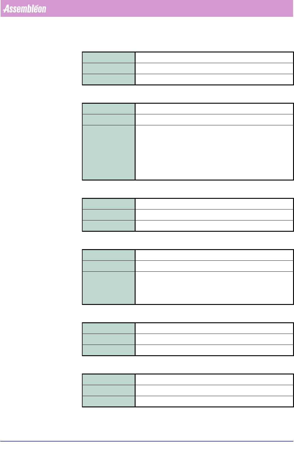
number of leads at side north/south
check leads ew
number of leads at side east/west
check thickness
component thickness
light level
Field type Integer
Range 0 - 100
Description Number of leads at each north/south side
Field type Integer
Range TRUE | FALSE
Description If TRUE, then the vision system will check the number of leads at
both the east/west side as stated in the <number of leads at side
east/west> field.
If FALSE, then the vision system will count the number of leads at
each east/west side and check that both numbers match.
For components that don’t have east/west leads by component type
definition, this field is ignored.
Field type Integer
Range 0 - 100
Description Number of leads at each east/west side
Field type Integer
Range TRUE | FALSE
Description If TRUE, then the vision system will use the value that is stated in the
<component thickness> field.
If FALSE, then the vision system will use a default value as defined
for the concerned component type.
Field type Real
Range 0.000 - 6.000 (mm)
Description Component thickness
Field type Integer
Range 0 - 100
Description Light level setting for an adequate measuring of the component.
4022 591 96082 User Reference Manual
02.02 FCM Multiflex 6-59
Product Change Over
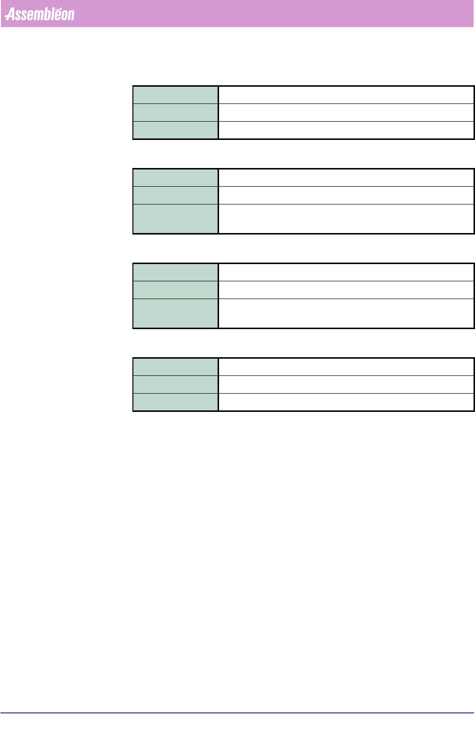
ruler threshold
maximum X offset
maximum Y offset
maximum PHI offset
Field type Integer
Range 0 - 255
Description Ruler threshold setting for an adequate measuring of the component.
Field type Real
Range 0 - 1.00 (mm)
Description Maximum permissible difference in X-direction between nominal
component centre line and measured component centre line.
Field type Real
Range 0 - 1.00 (mm)
Description Maximum permissible difference in Y-direction between nominal com-
ponent centre line and measured component centre line.
Field type Real
Range 0 - 6 (degrees)
Description Maximum permissible component rotation.
Product Change Over
User Reference Manual 4022 591 96082
6-60 FCM Multiflex 02.02
6.7.4 Large Asymmetric Components
6.7.4.1 Package Classes
From software FC5.1 on, the FCM Multiflex package type database contains the SMD
info files for large asymmetric component types as well.
In this case, component package types are grouped logically into package classes.
Each package class represents a number of component package types with the
same vision characteristics.
For example, package class SO goes for SO8, SOM16, SOL20.
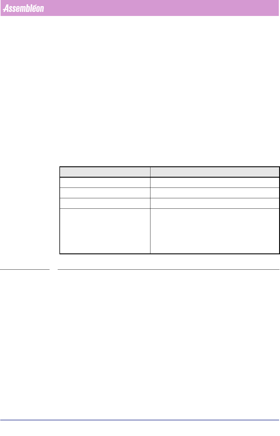
A package class is built up from several information blocks. Each information block
contains parameters for specific vision aspects.
To get an impression of what data are involved in the various information blocks,
see the table below
.
TABLE 6-24
,QIRUPDWLRQEORFN 'HVFULSWLRQ
[GENERAL] General vision file aspects
[PACKAGE] General items for a package class
[2D] Illumination information for 2D
[NORTH] or
[SOUTH] or
[NORTH/SOUTH] and/or
[EAST] or
[WEST] or
[EAST/WEST]
The lead description for one or more lead groups