FCM_User Reference Manual.pdf.pdf - 第256页
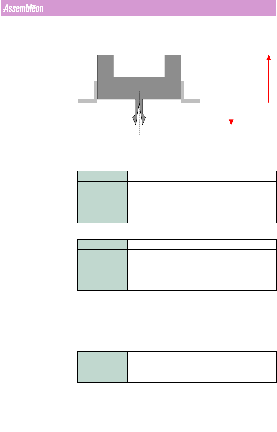
Pr oduc t Ch ang e Ov er User Re f eren ce Manu al 4022 591 960 82 6-64 FCM M ult ifle x 02.02 FIGURE 6-25 Body dim ens ion s, h ei gh t and d epth ▼ REJECT_ LEVEL ▼ BOD Y_T OLERAN CE [2D] This pa r ameter block defines …
4022 591 96082 User Reference Manual
02.02 FCM Multiflex 6-63
Product Change Over
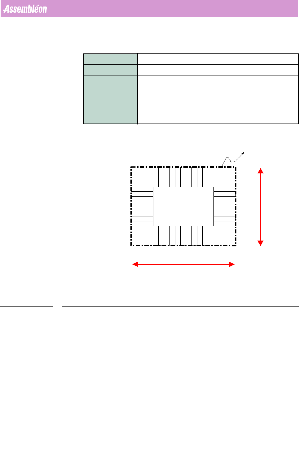
▼ BODY_DIMENSION
FIGURE 6-24 Body dimensions, footprint outline
Field type Real
Range > 0 (mm)
Description <footprint_X> <footprint_Y> <package_height> [package_depth]
See FIGURE 6-24 and FIGURE 6-25.
Describes the dimensions of the circumscribing box of the compo-
nent footprint (the leads are important and not the package as such).
footprint_X
North
West
South
East
Footprint outline
footprint_Y
Product Change Over
User Reference Manual 4022 591 96082
6-64 FCM Multiflex 02.02
FIGURE 6-25 Body dimensions, height and depth
▼
REJECT_LEVEL
▼ BODY_TOLERANCE
[2D]
This parameter block defines the illumination that will be used in a 2D vision meas-
urement.
▼
ILLUMINATION_TYPE
Field type Real
Range > 0 (mm resp. degrees)
Description <reject_level_X> <reject_level_Y> <reject_level_Phi>
The maximum allowed deviation from the ideal pick position in X-, Y-
and Phi-direction.
Field type Real
Range > 0 (mm)
Description <footprint_X_tolerance> <footprint_Y_tolerance>
Absolute dimensions for the tolerance on the size of the component
in X- and Y-direction.
Field type String
Range REFLECTION
Description The used illumination type.
package_height
package_depth
4022 591 96082 User Reference Manual
02.02 FCM Multiflex 6-65
Product Change Over
▼ LIGHT_LEVEL
▼ SKEW_DETECTION
[NORTH]
[SOUTH]
[NORTH/SOUTH]
[EAST]
[WEST]
[EAST/WEST]
These parameter blocks specify the lead information parameters for the various lead
groups and the vision processing parameter settings.
Lead Information Parameters
Lead information parameters are the parameters that define a lead group. If more
than one lead group exists (package class: SPECIAL), then these parameters are
numbered with an index to indicate which group of the parameter is valid.
The numbering sequence must be from left to right for the NORTH and SOUTH
descriptions and from top to bottom for EAST and WEST descriptions (FIGURE 6-26).
Field type Integer
Range 0 - 100 (%)
Description Defines the light level for REFLECTION in percentage of the maxi-
mum light level.
Field type Boolean
Range ON or OFF (= Default)
Description Checks whether the NORTH-SOUTH leads are perpendicular to the
EAST-WEST leads (lead-bending check).