FCM_User Reference Manual.pdf.pdf - 第239页
4022 591 960 82 Us er Reference Man ual 02.02 FC M Multif lex 6-47 Pr oduc t Ch ang e Ov er 6.6.1. 2 Algori thm In order to d etermine the alg orithm which should be used for calculating the X, Y , and Phi o ffs et s , i…
Product Change Over
User Reference Manual 4022 591 96082
6-46 FCM Multiflex 02.02
6.6 SMD Info Files
6.6.1 CLM
6.6.1.1 Introduction
In order to be able to align a component by laser alignment, it is necessary to have
all relevant information concerning this component available.
For each package type, this information is available in an SMD information file, the
so-called “SMD Info File”. The FCM Multiflex database you received with your FCM
Multiflex software package contains SMD information files for the most commonly
used component package types, ranging from type 0402 up to SO16. Each package
type out of the Package Type Data Base
1
is linked to a unique SMD info file.
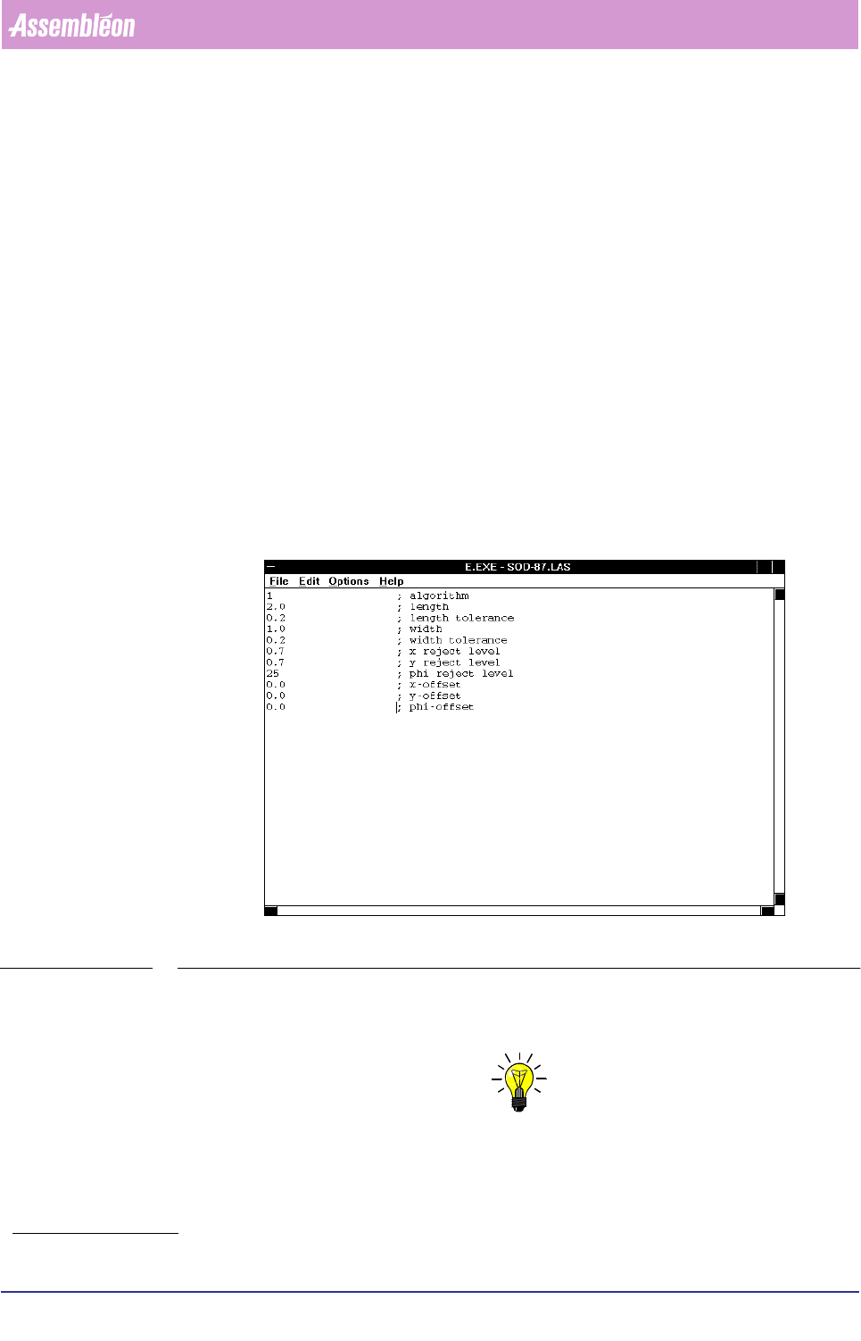
The supervisor or maintenance/service engineer has the possibility to edit a
specific SMD info file, using the [Edit SMD Info] function.
When editing, the user can either change the current values, or define a new SMD
info file type; see FIGURE 6-15.
FIGURE 6-15 Editing an SMD info file
When an existing SMD info file has been modified, it is advised to save it under a
new name. In this way, the original file will not be corrupted.
NOTE: Inform the PPS department when you have created a new SMD info file; in
this way they can use this new file name whenever new action specs should
be generated!
1. See the Package Type Data Base list.
4022 591 96082 User Reference Manual
02.02 FCM Multiflex 6-47
Product Change Over
6.6.1.2 Algorithm
In order to determine the algorithm which should be used for calculating the X, Y,
and Phi offsets, it is necessary to know how the component is positioned in the
laser beam.
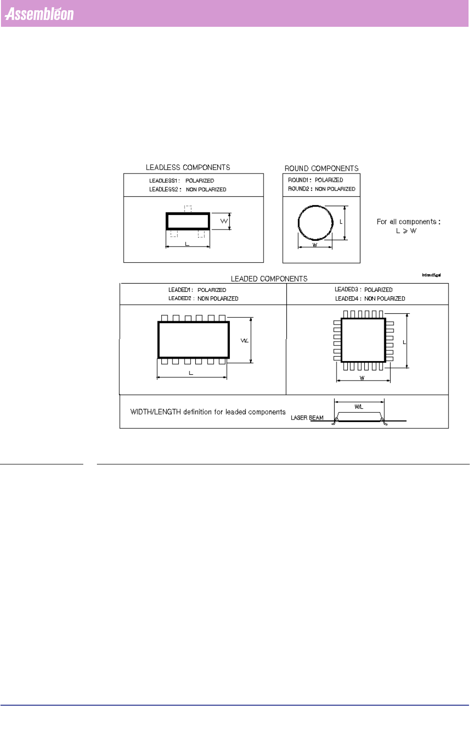
For this purpose we defined various component types; FIGURE 6-16.
FIGURE 6-16 Component types
Component Type Definitions
■ LEADLESS
A component type is defined as “LEADLESS” if it contains no leads, or all leads
remain beyond the laser beam.
In both cases, the component’s body determines its centre.
We define two leadless component types:
• LEADLESS 1 = polarized
• LEADLESS 2 = non-polarized
■ LEADED
A component type is defined as “LEADED” if the laser beam shines on one or
more (pair of) leads.
In this case, the component’s leads determines its centre.
Product Change Over
User Reference Manual 4022 591 96082
6-48 FCM Multiflex 02.02
We define four leaded component types:
• LEADED 1 = polarized, with leads on one or opposite body sides
• LEADED 2 = non-polarized, with leads on one or opposite body sides
• LEADED 3 = polarized, with leads on adjoining body side(s)
• LEADED 4 = non-polarized, with leads on adjoining body side(s)
■ ROUND
A component type is defined as “ROUND” if the component is round in the
radial direction.
NOTE: Round axial components, like MELFs, are defined as “ LEADLESS” components.
Only X and Y offsets are measured for round components.
We define two round component types:
• ROUND 1 = polarized
• ROUND 2 = non-polarized
6.6.2 Polarity Sensitivity
Polarized components will always be placed under the angles as specified in the
action spec (item mnt_phi in the MOUNT records).
Non-polarized components might be placed with 180 degrees offset to reduce the
alignment time.
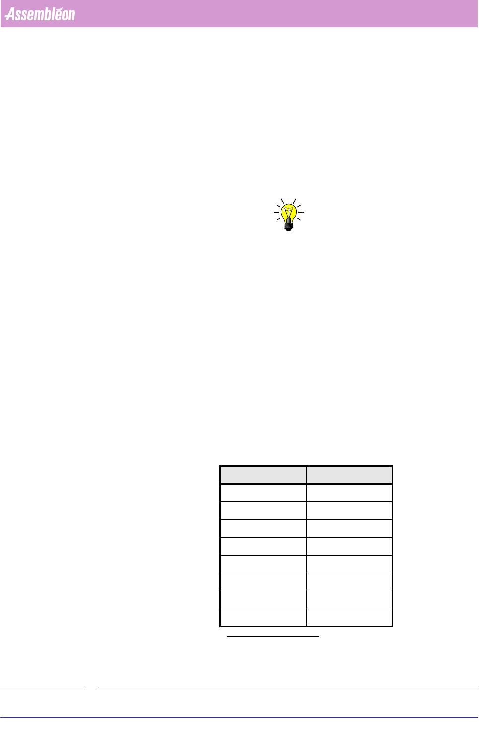
6.6.3 Algorithms’ Overview
Following table shows the relation between the various component types and the
algorithm to be used.
TABLE 6-20
&RPSRQHQWW\SH $OJRULWKP
LEADLESS 1 0
LEADLESS 2 128
LEADED 1 / RNET 1
a
a. Depending on the presence or non
presence of the RNET donglle.
LEADED 2 129
LEADED 3 2
LEADED 4 130
ROUND 1 3
ROUND 2 131