FCM_User Reference Manual.pdf.pdf - 第205页
4022 591 960 82 Us er Reference Man ual 02.02 FC M Multif lex 6-13 Pr oduc t Ch ang e Ov er REFPIN There is one line for the r eference pin posi tion. This position is f or the rang e of pr odu ction boar ds fr om 0.0 t …
Product Change Over
User Reference Manual 4022 591 96082
6-12 FCM Multiflex 02.02
<range> ::= <lower><upper>
<lower><upper> ::= range 77..590
<offset_1><offset_2> ::= range 0..300
Initial file
DEFAULT 81.0 390.0 NS 23.0 23.0
DEFAULT 0.0 81.0 SS 33.0 23.0
REFPIN 0.0 390.0 36.0
STRIP 87.0 101.5 NS 52.5 23.0
STRIP 50.0 87.0 SS 33.0 23.0
Explanation of the file:
DEFAULT
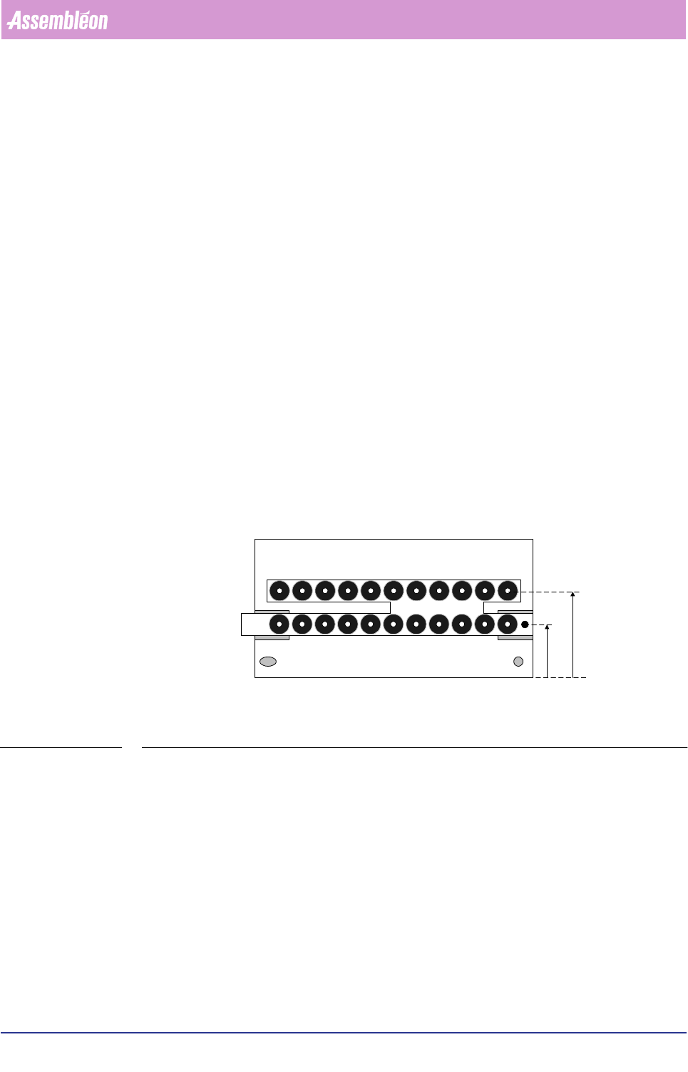
There are 2 default lines. The first is the default for the range of production boards
from 81.0 mm to 390.0 mm in Y. For these boards the default strip positions are
23.0 mm from the rear edge (N=north edge) and 23.0 mm from the front edge
(S=south edge).
FIGURE 6-6
The second default line is for the range of production boards from 0.0 mm to 81.0
mm in Y. For these boards the default strip positions are 33 mm from the front edge
(S=south edge, in figure S
F
2) and 23 mm from the front edge (S=south edge, in
figure S
F
1). These are the values for de dual calibration strip.
Do not edit these values because these defaults are the values (from the offline
preparation tool) that are used when none of the checkboxes are checked.
South east
corner
S
F
1
S
F
2
4022 591 96082 User Reference Manual
02.02 FCM Multiflex 6-13
Product Change Over
REFPIN
There is one line for the reference pin position. This position is for the range of
production boards from 0.0 to 390.0 mm in Y. The reference position in Y is 36.0
mm. When there is no value in the Action spec this value is used. This value is also
used when the checkbox “use default” is checked.
It is possible to enter default positions for 5 production board ranges in Y. Just add
a new line REFPIN and fill in the values for the range and the Y-position.
It is recommended to enter correct values in the Action spec, these values are then
used during calibration.
STRIP
Standard, there are two lines that work the same way as the lines DEFAULT.
However these values are only used when the checkbox “Use fixed alternatives” is
checked.
The values that are set in the initial files are made for customers who use the
carrier-kit. For production boards between 87.0 mm and 101.5 mm in Y the rear
calibration strip can interfere with the reference pin.
It is possible to enter default positions for 5 production board ranges in Y. Just add
a new line STRIP and fill in the values for the range and front and rear strip
position. Also add how the positions are measured (NS, from the rear (north) edge
and from the front (south) edge or SS, both from the front (south) edge).
NOTE: Strip positions are initially given by “DEFAULT” lines. The “STRIP” lines
only apply if the user has checked “Use fixed alternatives”
NOTE: Lines may be absent, in this case the following will be used if the board
width (Y) is out of range:
• “DEFAULT” present: default position
• “DEFAULT” absent: 23
Ranges are inclusive <lower> and exclusive <upper> boundary
Product Change Over
User Reference Manual 4022 591 96082
6-14 FCM Multiflex 02.02
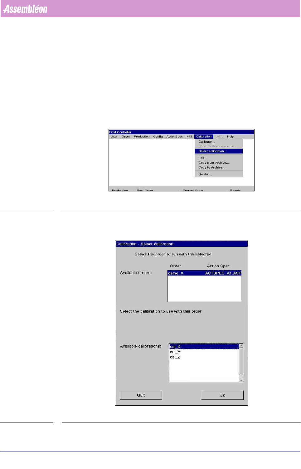
6.3 Manual Select Calibration File
(Producing with Previous Calibration File)
If the carriers used where calibrated previously it is possible use that previous cali-
bration file instead of performing a Multiflex calibration.
Go to
ÍCalibration ÍSelect calibration…
SCREEN 6-5
Screen appears.
SCREEN 6-6
In this dialog a suitable calibration set can be chosen for the order to be used.