FCM_User Reference Manual.pdf.pdf - 第40页
Hu man Inte rfac e User Re ference Manual 4022 5 91 96082 3-24 F CM Mult ifl ex 02.02 3.8.2.5 Enabling /Disabling Fiducial O ff set Check • S el ect [Fidu cial Offset C h eck] via th e [Options] m enu SCREE N 3-1 5 • S e…
4022 591 96082 User Reference Manual
02.02 FCM Multiflex 3-23
Human Interface
3.8.2.2 Error Recovery
Error recovery will take place on either one of the following conditions:
■ Automatic recovery: when [Continue production after DFA process error] is
enabled;
■ Manual recovery: when [Skip Action] is selected.
For description of error recovery options, see listing below.
TABLE 3-2
NOTE: The options mentioned before only relate to a fiducial measurement error.
If - for instance - the error message “ Fiducial not found” appears, selecting
one of these options is not relevant. In that case a manual recovery will be
required.
3.8.2.3 Run Time Options
Continue Production after DFA Process Error
When [Continue production after DFA process error]
has been selected,
production will automatically continue after a Fiducial Alignment process error.
3.8.2.4 Fiducial Offset Check (from version FC 6.1 onwards)
This option allows the user to specify a maximum allowed offset for fiducial meas-
urements. If the measured offset is larger than specified by the user, the FCM
Multiflex stops and an error message is generated:
BVM: Measured offset of <measured_offset> mm too large for fid=<fiducial_nr>,
circ=<circuit_nr>, indx=<index_nr>, brd=<carrier_nr>, pos_x=<board_pos_x>,
pos_y=<board_pos_y>.
Example:
BVM: Measured offset of 1.456 mm too large for fid=2, circ=1, indx=3, brd=1,
pos_x=184.850, pos_y=24.950
Selected Option Result
Disable Circuit No components will be mounted on the circuit where the DFA failed
No Correction There will be no offset or rotation correction applied to the circuits
where the DFA failed
Apply last FA transformation Apply offset or rotation correction based on the last FA transforma-
tion in this batch to the circuit where the DFA failed
Human Interface
User Reference Manual 4022 591 96082
3-24 FCM Multiflex 02.02
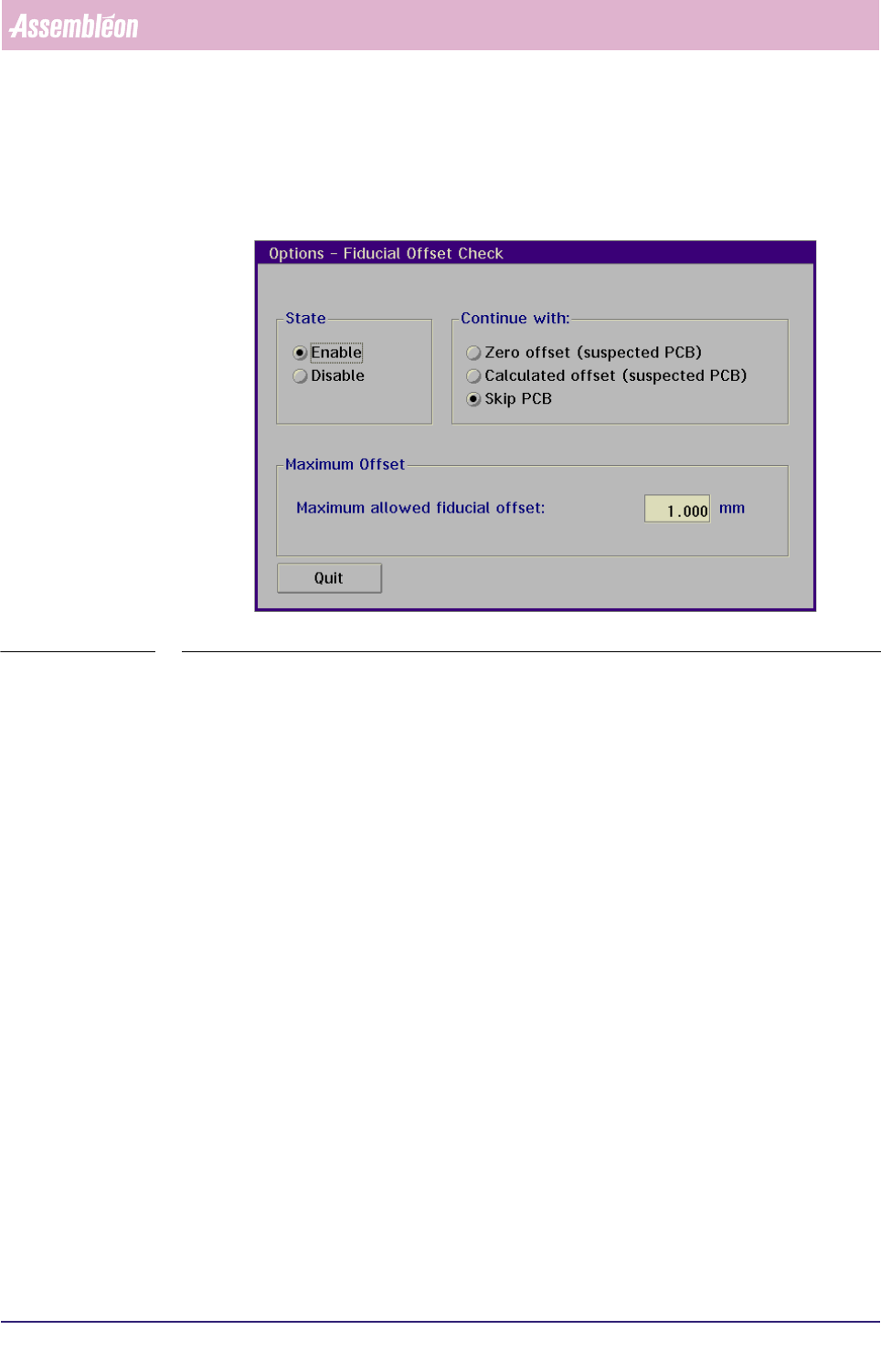
3.8.2.5 Enabling/Disabling Fiducial Offset Check
• Select [Fiducial Offset Check] via the [Options] menu
SCREEN 3-15
• Select [Enable] or [Disable] to enable or disable
3.8.2.6 Selecting Continuation Method
The following continuation methods can be selected:
• continue component placement on this board using zero offset
• continue component placement on this board using the calculated offset
• skip placement on this board
The selected continuation method will be used after selecting [Ok] in the error
message as described in this section. In all cases the boards will be marked as
"Suspected".
3.8.2.7 Specifying Maximum Offset
The user can enter the maximum allowed fiducial offset (range 0.000 mm – 2.000
mm). By default this value is set to 1.000 mm. It is advised not to use too small
values since this may generate too much offset errors. Setting this value too large
may still cause wrongly calculated offsets to be used for placement correction. It is
recommended to start with the default value and decrease in steps of 0.1 or 0.2
mm to an acceptable level for the customer.
4022 591 96082 User Reference Manual
02.02 FCM Multiflex 3-25
Human Interface
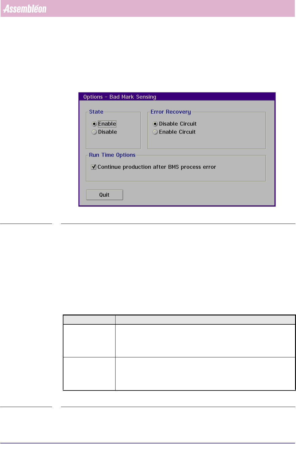
3.8.3 Badmark Sensing Settings
3.8.3.1 Enabling/Disabling the Badmark Sensing
■ Select [Bad Mark Sensing] via the [Options] menu
SCREEN 3-16
■ Select [Enable] resp. [Disable] to enable resp. disable badmark sensing
3.8.3.2 Error Recovery
In case the badmark sensing measurement fails, error recovery will take place on
either one of the following conditions:
■ Automatic recovery: when [Continue production after BMS process error] is
enabled;
■ Manual recovery: when [Skip Action] is selected.
■ For description of error recovery options, see listing below.
TABLE 3-3
Selected Option Result
Disable Circuit - If measurement is related to the master badmark, the system will measure all
local badmarks
- If measurement is related to a circuit badmark, the corresponding circuit is
disabled (component placement inhibited)
Enable Circuit - If measurement is related to the master badmark, the system will measure all
local badmarks
- If measurement is related to a circuit badmark, the corresponding circuit is
enabled (component placement executed)