FCM_User Reference Manual.pdf.pdf - 第195页
4022 591 960 82 Us er Reference Man ual 02.02 FC M Multif lex 6-3 Pr oduc t Ch ang e Ov er 6.2 Alternativ e Calibr ation T ooling P ar ameters 6.2.1 Calibration Strip Selection F or the corr ect Calibration strip length:…
Product Change Over
User Reference Manual 4022 591 96082
6-2 FCM Multiflex 02.02
6.1 Copy New as to FCM Multiflex Controller
Order Preparation
This section describes how to prepare new Action Specs for the use during a batch
change. It explains how to:
■ Copy a new Action Spec to the FCM Controller
■ Associate a new Action Spec with a System Calibration File
■ Associate a new Action Spec with a BVM Calibration File
■ Enter one or more orders
■ Schedule orders for a coming production period.
After the Order has been prepared, the Machine Setup can be performed.
6.1.1 Copying a New Action Spec to the FCM Multiflex Controller
An Action Spec is normally generated on floppy and delivered by the supplier or
PPS department. If the Action Spec is not present in the FCM Controller, it is
necessary to copy it first.
Procedure:
1. Change to Supervisor Level in the “User” pull-down menu.
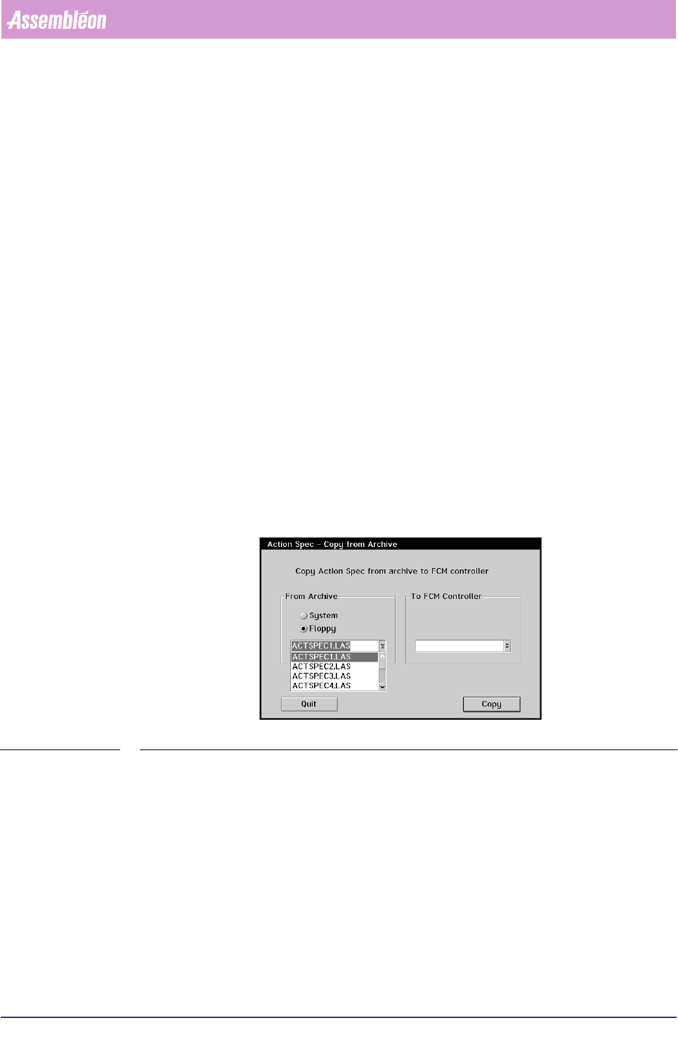
2. Select the “Copy from Archive” function in the “Action Spec” pull-down menu of
the main screen. The following dialogue will appear:
SCREEN 6-1 Copying a new Action Spec to the FCM Controller
3. Insert the floppy with the new Action Spec in the disk drive
4. Select {Floppy}
5. Tap the touch pad on the drop-down button in the “From Archive” box. A
scrollable list of all available Action Specs on the floppy will be displayed.
6. Select the requested Action Spec from the list.
7. If you want to rename the original Action Spec, enter the new file name in the
entry field of the “To FCM Controller” box. If not, the same name as the original
file will be used,
8. Select [Copy] or press <Enter> to perform the copy process,
9. Select [Quit] or press <Esc> to return to the Main Screen.
10.Change back to Operator Level in the “User” pull-down menu.
4022 591 96082 User Reference Manual
02.02 FCM Multiflex 6-3
Product Change Over
6.2 Alternative Calibration Tooling Parameters
6.2.1 Calibration Strip Selection
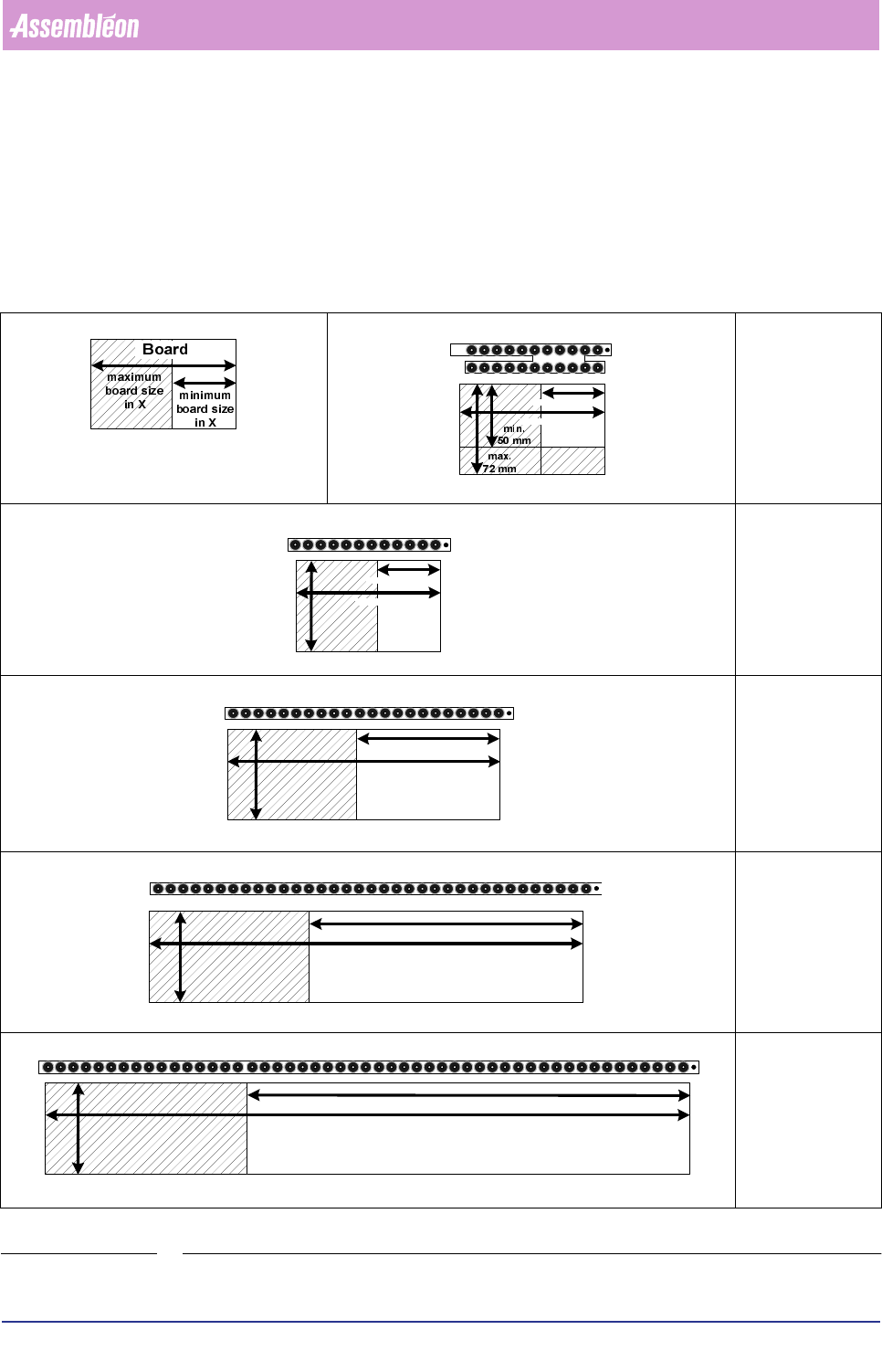
For the correct Calibration strip length: always select the smallest possible cali-
bration strip, refer to the following table for the correct length.
TABLE 6-1
Strip Dual
Board size
X
min
50 mm
X
max
110 mm
Y
min
50 mm
Y
max
72 mm
Strip L 125mm
Board size
X
min
50 mm
X
max
114 mm
Y
min
72 mm
Y
max
390 mm
Strip L 225mm
Board size
X
min
114 mm
X
max
214 mm
Y
min
72 mm
Y
max
390 mm
Strip L 355mm
Board size
X
min
214 mm
X
max
344 mm
Y
min
72 mm
Y
max
390 mm
Strip L 515mm
Board size
X
min
344 mm
X
max
500 mm
Y
min
72 mm
Y
max
390 mm
min. 50 mm
max. 114 mm
min. 50 mm
max. 114 mm
> 72
mm
min. 114 mm
> 72
mm
max. 214 mm
min. 214 mm
> 72
mm
max. 344 mm
min. 344 mm
> 72
mm
max. 500 mm
Product Change Over
User Reference Manual 4022 591 96082
6-4 FCM Multiflex 02.02
6.2.2 Calibration Strip Mounting on Alternative Positions on The
Board
The following sections describe the mount procedure in case of ‘special boards’.
Special boards are:
■ Boards smaller than 72 mm in Y direction (dual strip needed)
■ Boards with gaps on places where the clamps should be mounted
■ Boards with centring holes which are located beneath the calibration strips
■ Board and carrier combination in which case the calibration strip blocks the
reference pin (also known as temperature pin)
■ Board and carrier combination in which the clamps are blocked by support pins
In all these cases the calibration strips can be mounted on an alternative position.
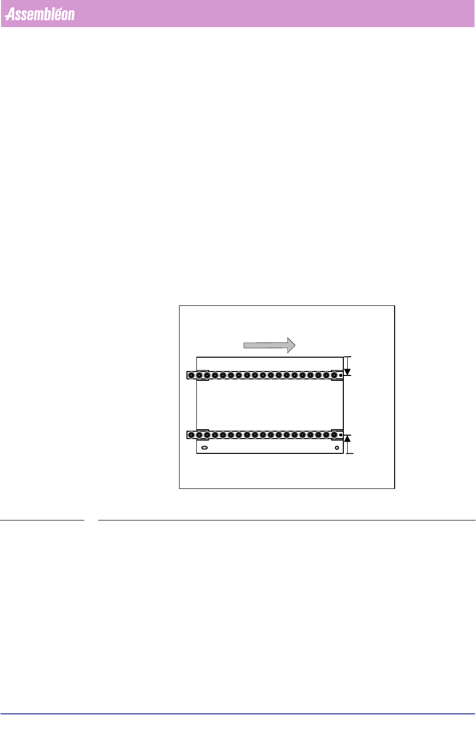
The default strip positions are 23mm from the front edge (S
F
) and 23mm from the
rear edge of the board (S
R
), see figure
FIGURE 6-2
If alternative strip positions are needed, first determine where the strips can be
mounted. In other words where would the strips not interfere with reference pins,
support pins and positioning pins.
6.2.3 Adjusting the Tool
First look at the figure to get familiar with the names of the different parts of the
adjusting tool. Then follow the flowchart to properly adjust the tool.
After preparing the calibration boards read 6.2.5 & 6.2.7 which explains how to
enter the alternative strip positions on the FCM.
Feeding direction into FCM
Top side
S
R
mm
S
F
mm
Front strip
Rear strip
South east
corner