FCM_User Reference Manual.pdf.pdf - 第274页
Pr oduc t Ch ang e Ov er User Re f eren ce Manu al 4022 591 960 82 6-82 FCM M ult ifle x 02.02 FIGURE 6-32 Ca lculation of the componen t ’ s ori gin ▼ For which com ponents do you use th is algorithm F or componen ts th…
4022 591 96082 User Reference Manual
02.02 FCM Multiflex 6-81
Product Change Over
• The search area as indicated in the drawings matches the reject level in the
SMD info file.
The SO algorithm
▼ How does it work
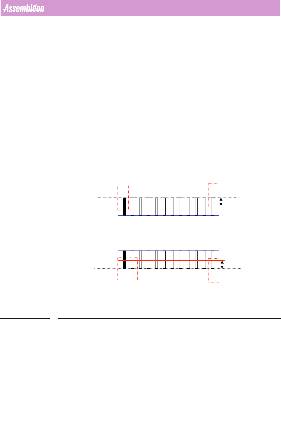
1. On the South side, find the first lead (black one in drawing) with a defined
search area and the last lead with a fine-search area.
2. Find the first lead (black one in drawing) and the last lead for the other side.
3. Measure all lead sides (edges) for both component sides (North/South).
4. Measure all lead ends for both component sides (North/South).
5. Check the pitch between the leads (if there is more than one lead a side).
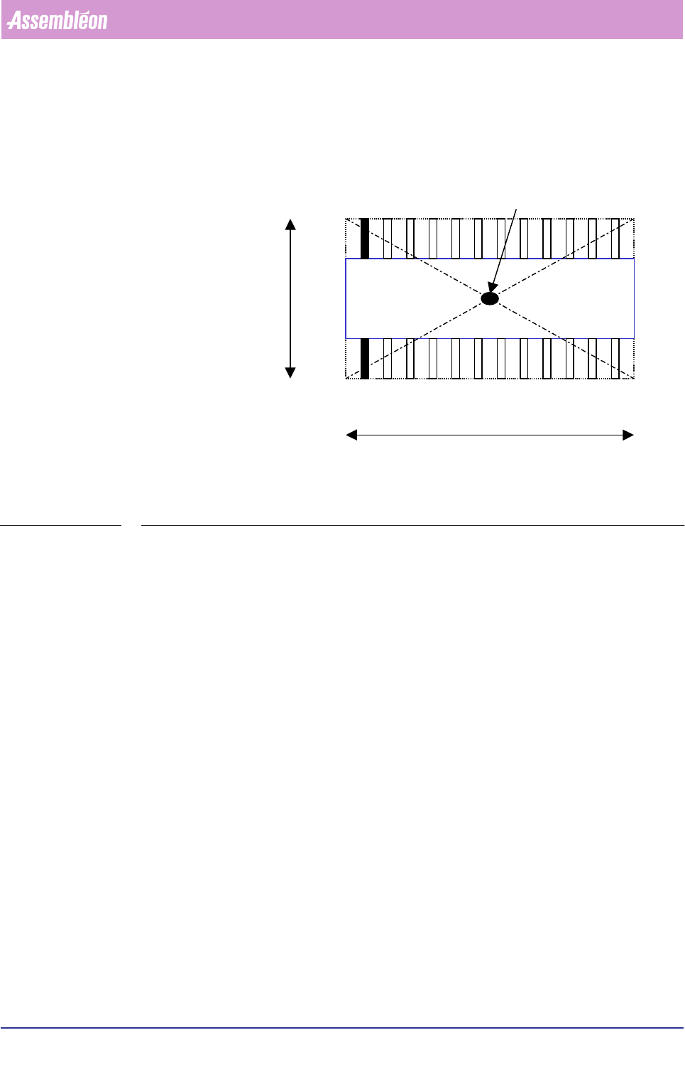
6. Calculate the centre and angle of the component origin with the information of
the lead sides and lead ends.
FIGURE 6-31 The SO algorithm measuring aspects
7. Check the distance between the middle of the first side (North) to the middle of
the second side (South).
8. Calculate the component origin based on the found vision origin and gravity
offsets.
Ruler
Ruler
Ruler offset
Ruler offset
Search area
Fine-search area Fine-search area
Fine-search area
NORTH
SOUTH
Product Change Over
User Reference Manual 4022 591 96082
6-82 FCM Multiflex 02.02
FIGURE 6-32 Calculation of the component’s origin
▼
For which components do you use this algorithm
For components that have leads on two sides (North and South), like:
• SO components;
• SSOP components;
• SOL components.
▼
General important information
• Ruler offsets are adjustable in the SMD info file; normally the value 3 is used
for most components (5 or 7 is also possible if you have components with a
bigger lead width). Ruler offset is in pixels; one pixel = 75x 75 µm. Always
use odd ruler widths in order to get valid mean calculation results.
• The body length and width in the SMD info file must be correct, because they
determine the positions of the leads together with the number of leads and
the lead pitch.
• For the ruler threshold, the value is normally between 20 and 30, but it
depends on the specific component type and the amount of light used.
• The search area as indicated in the drawings matches the reject level in the
SMD info file.
Component origin = vision origin
NORTH
SOUTH
Body length
Body width
4022 591 96082 User Reference Manual
02.02 FCM Multiflex 6-83
Product Change Over
The QFP algorithm
▼ How does it work
1. Find the first lead with a defined search area and last lead with a fine search
area of the South side.
2. Find the first lead and the last lead for the other sides (North, East, and West).
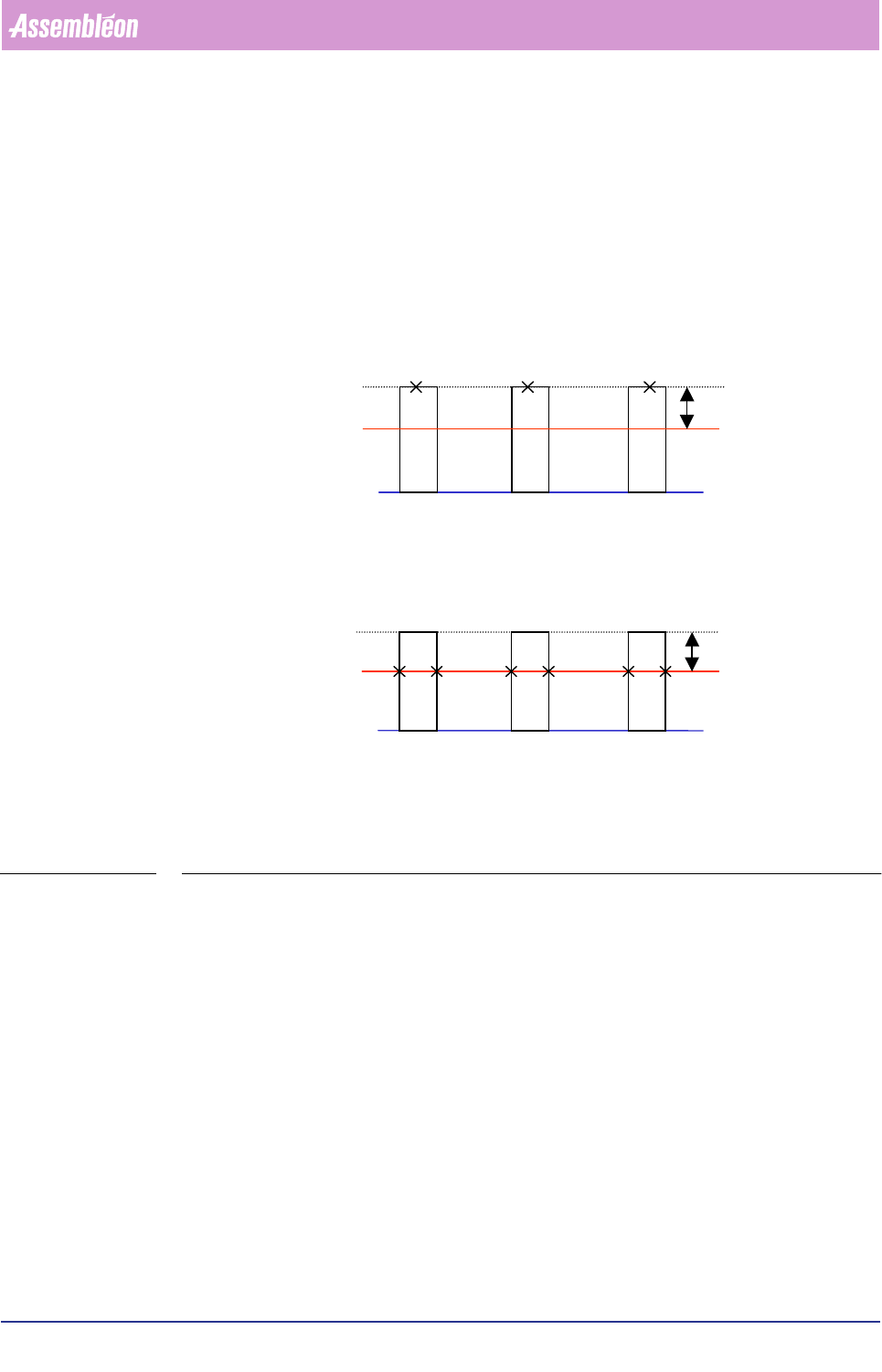
3. Depending on the component lead pitch, measure all the lead sides (edges) or
lead ends. If the pitch < 0.50 mm, then search for lead ends, otherwise search for
lead edges.
FIGURE 6-33 Measuring lead ends or lead edges, depending on the actual lead pitch
4. Check the pitch between the leads (if there is more than one lead a side).
5. Calculate the centre and angle of the component origin with the information of
the lead sides or lead ends (depending on the lead pitch, see Step3.) for all four
sides.
6. If the skew angle is required, measure the skew angle of the 4-sided component.
Fine lead search (looking for
lead ends)
Fine-rule
r
Ruler-offset
X = Lead end
Lead pitch < 0.50mm
Regular lead search (looking
for edges)
Ruler
Ruler-offset
X =
Edge
Lead pitch >= 0.50mm