QP-242E 工程师培训手册 (6.0).pdf.pdf - 第101页
FK-9F98-07 QP242E T raining Text for Service Engineers 6th edition 12. Placing Pressure Control Function Adjustment [ 3 / 4 ] Fuji Machine Mfg. Co., Ltd. Okazaki SMT Equipment Quality Assurance Dept. Technical Support Di…
FK-9F98-07 QP242E Training Text for Service Engineers
6th edition 12. Placing Pressure Control Function Adjustment [2/4]
Fuji Machine Mfg. Co., Ltd. Okazaki
SMT Equipment Quality Assurance Dept.
Technical Support Div. Section No.2
12-2
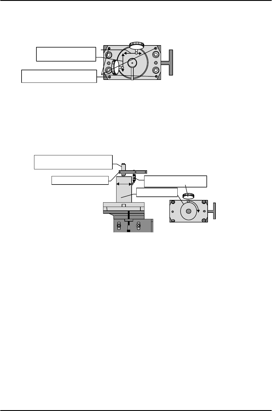
[12-4] Placing Pressure Control Device Leveling
1) Loosen the two bolts on the top cover of the control device and remove the cover.
2) Measure the front to back levelness and left to right levelness of the top surface of the bottom
plate with the dial gauge and use the hollow bolts at the four corners to level the plate.
Tolerance: Within 0 ± 0.01 mm
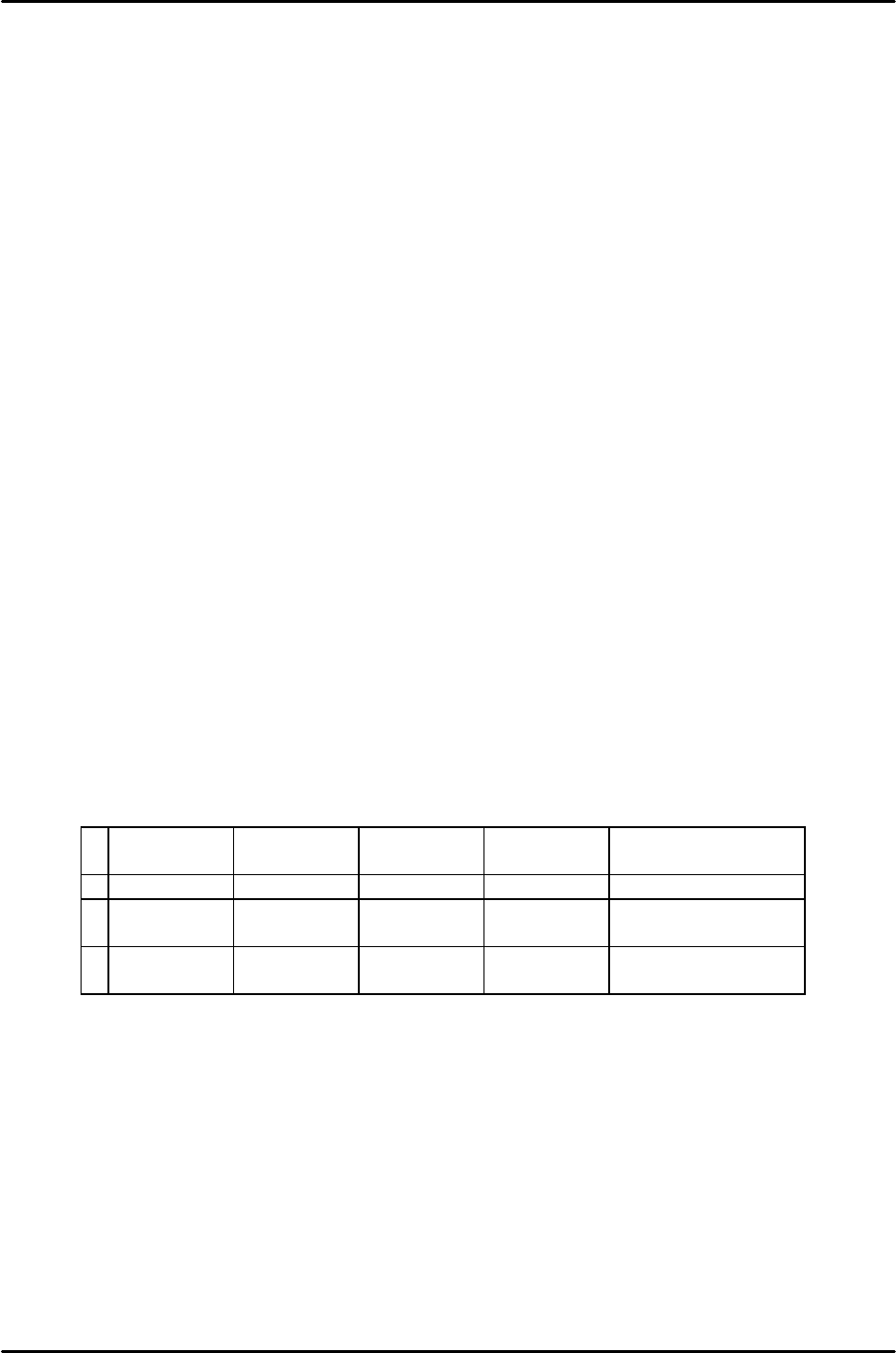
[12-5] PPC_Calibration_Position_X,Y
1) Attach the cylinder jig for measurement on the top of the bottom plate.
2) Use the plate jig to attach the dial gauge to the single holder.
3) Swing the dial gauge to measure the orbit of the cylinder jig and move the placement head via
jogging so that the amount of fluctuation in the dial gauge is within 0.01 mm.
4) In the position where the dial reads zero, perform the following command operation to
automatically enter the Proper data; [PROPER], [ETC], [ETC], [PLCING PRESS], [POSITION,
and [SET].
[12-6] Digital Indicator Settings
Operate the digital indicator to carry out selection of the sensor rated value and hold mode.
1) Cancel calibration prohibit (LOCK) and registration prohibit (LOCK).
After verifying that I/O OUT (Y04B: PRES CNTL LOCK) is in the “X” status carry out the next
operation and then cancel. (If the I/O is in the “0” status then disconnect rear terminal 21 and
22.)
Cancel the calibration prohibit (LOCK) status.
[*], [#], [1], [1], [#], [0], and [#]
Cancel the registration prohibit (LOCK) status.
[*], [#], [1], [2], [#], [0], and [#]
Since the prohibit (LOCK) status using the rear terminal and the prohibit (LOCK) status using
key input are both enabled (overlap is prohibited), cancel both.
2) Equivalent input calibration (By registering the sensor rated value, calibration of a load that is
not actually exerted can be carried out.)
Register the sensor rated value.
Register the rated output (mv/v/1 kgf) value of the calibrated load that is entered together with
the load cell. Take the rated output calculated in TEAC and enter it as shown below.
[1], [#], [Setting 1], [#], [Setting 2], [#]
Example: Rated output = 0.5361 mv/v 1.0 kgf
[1], [#], [0.536], [#], [1000.], [#]
Be careful of the decimal point position. (For decimal input press [*] when the lowest level digit
is blinking.)
View from the top of the placing pressure control device
Measure front to back
and left to right .
Adjust using the set screws
located at the four corners.
View from front of placing
pressure control device
View from top of the placing
pressure control device
Measure at position
where dial reads zero.
Plate swinging jig
Cylinder jig
Via jogging find the position
at which the dial reads zero.
FK-9F98-07 QP242E Training Text for Service Engineers
6th edition 12. Placing Pressure Control Function Adjustment [3/4]
Fuji Machine Mfg. Co., Ltd. Okazaki
SMT Equipment Quality Assurance Dept.
Technical Support Div. Section No.2
12-3
3) Register the zero point.
Register the zero point in the no load status (float load status, input 0).
[3], [#]
4) Select the digital filter and zero tracking.
[4], [#], [0 0], [#]
5) Select the analog filter and set the time lag.
Select the analog filter.
[*], [#], [2], [6], [#], [3], [#]
Set the analog filter time lag.
[*], [#], [2], [7], [#], [0 0 1], [#]
6) Select the hold mode.
Select the section set hold mode.
[9], [#], [3], [#]
7) Enable calibration prohibit (LOCK).
Enable the calibration prohibit (LOCK) status using key input.
[*], [#], [1], [1], [#], [1], [#]
Enable the registration prohibit (LOCK) status using key input.
[*], [#], [1], [2], [#], [1], [#]
(If rear terminal number 21 and 22 are disconnected then return to the original status.)
If zero does not display as the digital indicator value (no load status) then carry out steps 1, 3, and 7
in that order.
[12-7] Load Cell Calibration Check
This must be carried out after the digital indicator zero point has been adjusted.
1) Remove the device top cover and plate and set each load jig.
2) Verify that the amount of deviation of each load is within 10 g and that the difference between the
minimum and maximum amount of deviation is within 10 g. If the amount of deviation exceeds 10 g
then replace the load cell.
250g
difference
500g
difference
750g
difference
1000g
difference
Result
1 259g (+9) 504g (+4) 749g (-1) 1000g (0) Load cell OK
2 255g (+5) 504g (+4) 748g (-2) 994g (-6) Load cell NG
(Min, Max)
3 262g (+12) 511g (+11) 758g (+8) 1008g (+8) Load cell NG
(amount of deviation)

FK-9F98-07 QP242E Training Text for Service Engineers
6th edition 12. Placing Pressure Control Function Adjustment [4/4]
Fuji Machine Mfg. Co., Ltd. Okazaki
SMT Equipment Quality Assurance Dept.
Technical Support Div. Section No.2
12-4
[12-8] Placing Pressure Calibration Measurement
1) Set the nozzle installed on the module on which the pressure device is installed.
* Since specification of the nozzle name is required when placing pressure control
is
used, confirm that the nozzle name has been set. Measure in the nozzle change
status using the nozzle change command. Do not measure after detaching the
nozzle by hand.
2) All nozzles will be measured if the nozzle used for placing pressure control is not specified.
Verify that the Nozzle_Type item in the nozzle data of all nozzles is set to “64”.
3) After PPC_Calibration_Position_X and Y are measured exit the Proper data display
screen. By exiting the Proper data screen the Proper data is transmitted from the ICM to the
SCU board of each module. (The ICM extracts only the servo count from each module for
measurement. The set Proper data are held by the ICM when measurement is carried out.)
4) Enter the Proper data display screen again. Press [ETC], [ETC], [PLCING PRESS], [NZL
CHANGE], set the number of the measurement nozzle, then after the change over to the START
ready status press [MEASUREMENT] and START to begin measurement. Measurement is
carried out 30 times for the pressing force of each two points respectively.
5) Once measurement is finished if the 3D.V value displayed on the screen is within 10.0 then
measurement is complete. If it is more than 20.0 the machine will automatically erase the
measured value. However, care should be exercised since the tolerance range is within 10.0.
Press [YES] to save the measured value.
S.C.: Spring_const (spring constant obtained from measurement)
I.P: Init_Pressure (initial pressure obtained from measurement)
3D.V: Average 3sigma value after measurement (within 10.0)
Valid range Min gf, Max gf: 120 ~ 1200 g (guaranteed)
6) Return to [NZL CHANGE] and then change the measurement nozzle and measure again using
the same procedure. Carry out measurement using all nozzles.
7) Calibration result tolerance range
1: Additional pressure variation 3 sigma 10 g
2: Additional pressure range 120 ~ 1200 guaranteed
(An error will not be output even if the pressure is out of
range so check during measurement)
• Adjust the calibration result of Min to about 100 ~ 110 g.
Check the following points if the measurement result is out of range.
1: If the variation in the additional pressure is too large
(1) Check that movement is smooth when the nut is moved up and down.
à Make sure that the set status of the up/down spring is natural. The set status of the
spring will have a stiff feel once it is installed.
à Make sure there is not a stiff feel in the spline when the up/down spring is released.
If the spring is defective then replace it.
(2) Verify that the vacuum mechanism works smoothly.
à Replace it if defective.
2: If the additional pressure is out of range
(1) Verify that the add pressure sensor position is the same as the position from
adjustment.
à Verify that the sensor position is in compliance with the values used in adjustment
since the additional pressure range will be offset by sensor position adjustment.
(2) Check that the up/down spring is not excessively bent or stretched.
à In some instances the spring constant will not be exact. If so replace the spring.
After Proper data measurement is completed transmit the Proper data from the machine to F4G.