QP-242E 工程师培训手册 (6.0).pdf.pdf - 第132页
FK-9F98-07 QP242E Training Text for Service Engineers 6th edition 15. Digital Amplifier Parameter Chart [ 4 / 4 ] Fuji Machine Mfg. Co., Ltd. Okazaki SMT Equipment Quality Assurance Dept. Technical Support Div. Section N…

FK-9F98-07 QP242E Training Text for Service Engineers
6th edition 15. Digital Amplifier Parameter Chart [2/4]
Fuji Machine Mfg. Co., Ltd. Okazaki
SMT Equipment Quality Assurance Dept.
Technical Support Div. Section No.2
15-2
QP242E Digital amplifier parameter chart (Front device module)
Axis
SVA1
SVA2
SVA3
SVA4
Parameter No. Default Y X Q Z
*Cn−03 0 − − − −
Cn−04
400
*1
500
300
450
Cn−05 2000
*2
800 600 700
*Cn−06
max
−
−
−
−
*Cn−07 10 − − − −
Cn−08 max 316 300 310 317
Cn−09 max 316 300 310 317
Cn−0A 2048 2048 2048 2048 2048
*Cn−0B 0 − − − −
Cn−0C 200 200 200 200 200
Cn−0D 0 0 0 0 0
Cn−0E 0 0 0 0 0
Cn−0F 0 0 0 0 0
Cn−10 200 200 200 200 200
Cn−11 2048 4000 2000 2048 2048
Cn−12 0 0 0 0 0
Cn−15 100 100 100 100 100
Cn−16 50 50 50 50 50
Cn−17
400
*3
1000
500
600
Cn−18
0
0
0
0
0
Cn−19 0 0 0 0 0
*Cn−1A 4000 − − − −
*Cn−1B 7 − − − −
Cn−1C 0 0 0 0 0
*Cn−1D 0 − − − −
*Cn−1E 100000 − − − −
*Cn−1F 0 − − − −
*Cn−20 100 − − − −
*Cn−21 0 − − − −
Cn−22 50 50 50 50 50
Cn−23 5 5 5 5 5
*Cn−24 4 − − − −
*Cn−25 1 − − − −
*Cn−26 0 − − − −
Cn−27 0 0 0 0 0
Cn−28 100 100 100 100 100
Cn−29 0 0 0 0 0
Cn−2A 10 10 10 10 10
Cn−2B 100 100 100 100 100
Cn−2C 0 0 0 0 0
*Cn−2D 0 − − − −
*Cn−2E 0 − − − −
Cn−2F 57344 57344 57344 57344 57344
Cn−30 12499 12499 12499 12499 12499
Cn−31 57344 57344 57344 57344 57344
Cn−32 12499 12499 12499 12499 12499
Cn−33 0 0 0 0 0
Cn−34 0 0 0 0 0
Cn−35 0 0 0 0 0
Cn−36 0 0 0 0 0
Cn−37 0 0 0 0 0
*Cn−38 0 0 0 0 0
The section marked * will be transferred automatically from the machine during auto operation.
Values do not always match the default value in the chart.
*1 For 600mm modules: enter 500. For 800mm modules, enter 450.
*2 For 600mm modules, enter 1200. For 800mm modules, enter 1000.
*3 For 600mm modules, enter 2650. For 800mm modules, enter 2000.
FK-9F98-07 QP242E Training Text for Service Engineers
6th edition 15. Digital Amplifier Parameter Chart [3/4]
Fuji Machine Mfg. Co., Ltd. Okazaki
SMT Equipment Quality Assurance Dept.
Technical Support Div. Section No.2
15-3
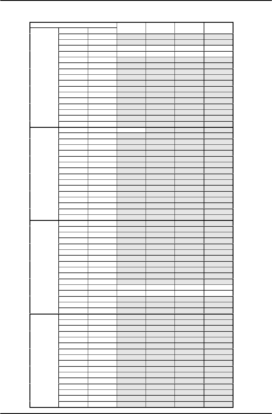
QP242E Digital amplifier parameter chart (Rear device module)
Axis
SVA1
SVA2
SVA3
SVA4
Bit Default Y X Q Z
0 0 0 0 0 0
1 0 0 0 0 0
2 0 1 1 1 1
3 0 1 1 1 1
4 0 0 0 0 0
5 0 0 0 0 0
6 0 0 0 0 0
Cn−01 7 1 1 1 1 1
8 0 0 0 0 0
9 0 0 0 0 0
A 0 0 0 0 0
B 0 0 0 0 0
C 0 0 0 0 0
D 0 0 0 0 0
E 0 0 0 0 0
F 0 0 0 0 0
0
0
1
0
0
0
1 0 0 0 0 0
2 0 0 0 0 0
3 0 0 0 0 0
4 0 0 0 0 0
5 0 0 0 0 0
6 0 0 0 0 0
Cn−02 7 0 0 0 0 0
8 0 0 0 0 0
9 0 0 0 0 0
A 0 0 0 0 0
B 0 0 0 0 0
C 0 0 0 0 0
D 0 0 0 0 0
E 0 0 0 0 0
F 0 0 0 0 0
0
0
0
0
0
0
1 0 0 0 0 0
2 0 0 0 0 0
3 0 0 0 0 0
4 0 0 0 0 0
5 0 0 0 0 0
6 0 0 0 0 0
Cn−13 7 0 0 0 0 0
8 0 0 0 0 0
9 0 0 0 0 0
A 0 0 0 0 0
B 0 1 1 1 1
C 0 1 1 1 1
D 0 0 0 0 0
E 0 0 0 0 0
F 0 0 0 0 0
0
0
0
0
0
0
1 0 0 0 0 0
2 0 0 0 0 0
3 0 0 0 0 0
4 0 0 0 0 0
5 0 0 0 0 0
6 0 0 0 0 0
Cn−14 7 0 0 0 0 0
8 0 0 0 0 0
9 0 0 0 0 0
A 0 0 0 0 0
B 0 0 0 0 0
C 0 0 0 0 0
D 0 0 0 0 0
E 0 0 0 0 0
F 0 0 0 0 0
FK-9F98-07 QP242E Training Text for Service Engineers
6th edition 15. Digital Amplifier Parameter Chart [4/4]
Fuji Machine Mfg. Co., Ltd. Okazaki
SMT Equipment Quality Assurance Dept.
Technical Support Div. Section No.2
15-4
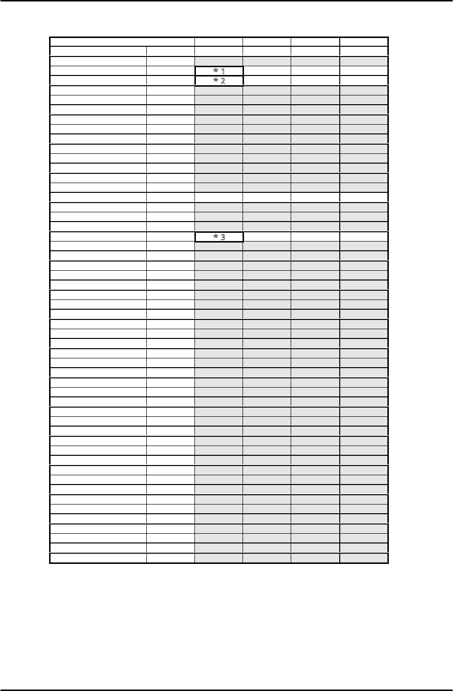
QP242E Digital amplifier parameter chart (Rear device module)
Axis
SVA1
SVA2
SVA3
SVA4
Parameter No. Default Y X Q Z
*Cn−03 0 − − − −
Cn−04
400
*1
500
300
450
Cn−05
2000
*2
800
600
700
*Cn−06
max
−
−
−
−
*Cn−07 10 − − − −
Cn−08 max 316 300 310 317
Cn−09 max 316 300 310 317
Cn−0A 2048 2048 2048 2048 2048
*Cn−0B 0 − − − −
Cn−0C 200 200 200 200 200
Cn−0D 0 0 0 0 0
Cn−0E 0 0 0 0 0
Cn−0F 0 0 0 0 0
Cn−10 200 200 200 200 200
Cn−11 2048 4000 2000 2048 2048
Cn−12 0 0 0 0 0
Cn−15 100 100 100 100 100
Cn−16 50 50 50 50 50
Cn−17
400
*3
1000
500
600
Cn−18
0
0
0
0
0
Cn−19 0 0 0 0 0
*Cn−1A 4000 − − − −
*Cn−1B 7 − − − −
Cn−1C 0 0 0 0 0
*Cn−1D 0 − − − −
*Cn−1E 100000 − − − −
*Cn−1F 0 − − − −
*Cn−20 100 − − − −
*Cn−21 0 − − − −
Cn−22 50 50 50 50 50
Cn−23 5 5 5 5 5
*Cn−24 4 − − − −
*Cn−25 1 − − − −
*Cn−26 0 − − − −
Cn−27 0 0 0 0 0
Cn−28 100 100 100 100 100
Cn−29 0 0 0 0 0
Cn−2A 10 10 10 10 10
Cn−2B 100 100 100 100 100
Cn−2C 0 0 0 0 0
*Cn−2D 0 − − − −
*Cn−2E 0 − − − −
Cn−2F 57344 57344 57344 57344 57344
Cn−30 12499 12499 12499 12499 12499
Cn−31 57344 57344 57344 57344 57344
Cn−32 12499 12499 12499 12499 12499
Cn−33 0 0 0 0 0
Cn−34 0 0 0 0 0
Cn−35 0 0 0 0 0
Cn−36 0 0 0 0 0
Cn−37 0 0 0 0 0
*Cn−38 0 0 0 0 0
The section marked * will be transferred automatically from the machine during auto operation.
Values do not always match the default value in the chart.
*1 For 600mm modules: enter 500. For 800mm modules, enter 450.
*2 For 600mm modules, enter 1200. For 800mm modules, enter 1000.
*3 For 600mm modules, enter 2650. For 800mm modules, enter 2000.