QP-242E 工程师培训手册 (6.0).pdf.pdf - 第124页
FK-9F98-07 QP242E Training Text for Service Engineers 6th edition 13. MTU 71E Adjustment [ 22 /24] Fuji Machine Mfg. Co., Ltd. Okazaki SMT Equipment Quality Assurance Dept. Technical Support Div. Section No.2 13- 22 [1 3…
FK-9F98-07 QP242E Training Text for Service Engineers
6th edition 13. MTU 71E Adjustment [21/24]
Fuji Machine Mfg. Co., Ltd. Okazaki
SMT Equipment Quality Assurance Dept.
Technical Support Div. Section No.2
13-21
1) From the operation panel press [PROPER], [DEVICE], [ORG.POS. X/Y], and select the desired
tray. Then specify the initial level to be measured [1] and press START. Once the TZ-axis
moves to the measurement jig height then set the measurement jig (ABHPJ0520) at both
position 101 and 102 on the first level.
2) Return to the previous display screen and select [MANUAL], [X1,Y1], and press START to
execute positioning of number 101.
NOTE: Always select [MANUAL] for the first level.
3) Move the placing head via inching until the center of the mark on the jig is in the center of the
crosshairs that display on the mark camera image screen. Once movement is finished then
press [SET] to carry out automatic entry of the Proper data.
4) Likewise measure [X2,Y2] in the same manner using automatic entry.
5) Move both jigs from the first level to the second level and reset. This time select [AUTO] instead
of [MANUAL], specify the second level [2] and then press START.
6) The machine automatically measures both Proper data items for the second level in succession.
At the same time that measurement finishes the tray plate returns to the storage position,
descends to the first level and stops. Reset the jigs at the next level and use the same procedure
to complete automatic measurement of the Proper data for all devices.
NOTE: If a vision processing error occurs reset the error, return to the [MANUAL] / [AUTO]
display and carry out measurement using the manual operation. The tray will
remain in the given status.
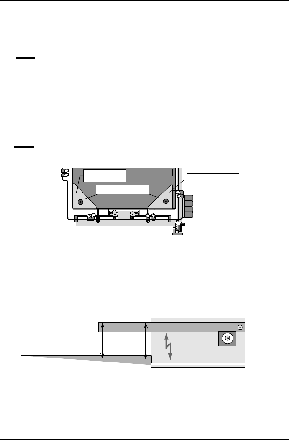
[13-56 ] Reject Parts Conveyor Adjustment and Height Adjustment
1) Adjust the reject parts conveyor in accordance with the adjustment procedures manual for
the reject parts conveyor (FK-9C88-67). However, be aware that belt tension adjustment "1"
on the MTU71 is not 18 to 19 mm but 13 to 14 mm.
2) With the MTU71 unit connected to the placing module, adjust the height of the conveyor so
that the distance from the machine base to the top of the reject parts conveyor side plate is
201 mm. Check the height at both the end of the conveyor and in the middle of the conveyor
and install such that it is parallel with the base.
MTU7
Reject parts conveyor
Machine
base
201mm
Shuttle forward limit position
Device
number 102
Device number 101
Measurement jig plate
FK-9F98-07 QP242E Training Text for Service Engineers
6th edition 13. MTU 71E Adjustment [22/24]
Fuji Machine Mfg. Co., Ltd. Okazaki
SMT Equipment Quality Assurance Dept.
Technical Support Div. Section No.2
13-22
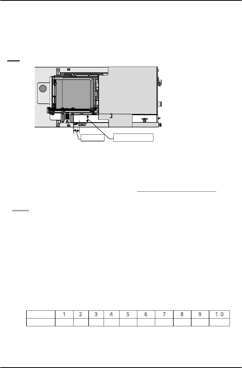
[13-57 ] MTU_Parts_Eject_Pos.CV_X,Y Measurement
1) Set the nozzle jig.
2) Move the placing head to the position where the center of the tip of the nozzle jig is 50 mm
from the width center of the reject parts conveyor in the X-direction and 50 mm from the rear
edge of the conveyor in the Y-direction.
3) This position is MTU_Parts_Eject_Pos.CV_X, Y. Use the following command operation to
automatically enter the values in Proper data: [PROPER], [ETC], [REJECT POS.],
[CONVEYOR], and [SET].
Note: The maximum width of parts that can be discarded on the reject parts conveyor is 50 mm.
[13-58 ] Empty Tray Discard Box Existence Switch Check
1) After selecting [POSITION], [MTU], SHUTTLE], and [RETRACT] then press START to move
the shuttle to the retract limit. Once this is done press [TRAYORG] to raise the Z-axis.
2) Pull the empty tray discard box away from the limit switch position and then tightly secure the
safety door.
3) If the reset button cannot be used to cancel the "Safety door opened/MTU BOX" error that
displays then the check switch is working properly. If the error can be canceled then search for
the cause.
NOTE: Carry out this check after all Proper data values have been measured.
[13-59] Tray Pickup Check Sensor Settings
1) Summary
The tray pickup check sensor is used when a tray is being discarded to monitor whether the
tray is picked by the remover. If a tray is dropped this sensor will respond and the machine
will stop immediately. This measure is to prevent damage to the machine. Be aware that
the immediate machine stop may cause the parts in the tray to become scattered. Note also
that this function is an option.
2) Settings
a. Device switch settings
1. While pressing the convex button in the lower center of the amp panel, pull the panel unit
forward. (The machine power must be cut and the panel display must be off before doing
this.)
2. Set the ten individual switches as shown in the table below.
No.
1 2 3 4 5 6 7 8 9 10
Setting OFF ON ON ON OFF OFF OFF OFF OFF OFF
3. Once the dip switch settings have been made return the panel to its original status.
50mm
Machine
★
Conveyor center

FK-9F98-07 QP242E Training Text for Service Engineers
6th edition 13. MTU 71E Adjustment [23/24]
Fuji Machine Mfg. Co., Ltd. Okazaki
SMT Equipment Quality Assurance Dept.
Technical Support Div. Section No.2
13-23
b. Zero shift value setting
Turn the machine power on and use the following procedure to make the setting.
1. Move from the measurement mode in which the measured value is displayed, to the
setting mode by pressing the arrow key. 1-H displays in the top level and the zero shift
value displays in the lower level.
2. Set the zero shift value to -1 mmHg.
(The value can be changed using the up/down key.)
3. The zero shift value is entered when the arrow key is pressed after which 1-H will display.
4. Set this value to zero. (If the value is zero to begin with this can be left as it is.)
5. Press the arrow key twice to return the mode to the measurement mode.
This completes the tray pickup check sensor settings.
NOTE: This function can be switched on and off by means of a Proper data setting. However,
when this function is switched on, the tray discard operation cycle time will be 280 to
290 ms longer than the existing cycle time.
• ON/OFF switching procedure
To set to ON add 4096 to Proper data item PLM?_Machine_Status (MQ2?_MASA) and then
transmit the Proper data to the machine. The "?" denotes the module number. Also note
that if this is not input the tray pickup check function will be OFF.
3) Operation check of the tray pickup check sensor
This operation check is used to verify that the tray pickup check sensor does not erroneously
detect a tray. It applies when the settings outlined in 2) above have been made. The tray
pickup check sensor will go off, the tray will be considered as having been dropped, and the
machine will enter the emergency stop status if the vacuum pressure differential (pressure
when the remover vacuum leaks completely versus the pressure when a tray is picked) falls
below 1 (mmHg). Although the cases in which this would actually be used are extremely
limited, the following precautions would apply if an ultra lightweight tray (less than 40 g)
were being used for which pickup is possible even in the presence of a slight vacuum pressure
differential (2 - 3 mmHg).
If the vacuum pressure differential does not stabilize and the tray pickup sensor is chattering
this may cause an unnecessary emergency stop of the machine to occur. If so use a dummy
tray, for which pickup is possible in the presence of a pressure differential of 2 to 3 (mmHg), to
carry out a tray pickup check sensor detection test.
The procedure for conducting such a test is described below.
a. First, use the unit operation command to chuck the remover to the head.
b. Set the MY02B REMOVER VACUUM I/O to ON.
c. Set the MY03F TRAY PKUP OSET to ON.
d. Verify that the MX027 TRAY PKUP CHK I/O is always OFF (no chattering) when the
remover has nothing picked.
e. Manually pick the dummy tray with the remover.
f. Verify that the MX027 TRAY PKUP CHK I/O is always ON (no chattering) when the
dummy tray is picked.
This completes the check operation.