QP-242E 工程师培训手册 (6.0).pdf.pdf - 第117页
FK-9F98-07 QP242E Training Text for Service Engineers 6th edition 13. MTU 71E Adjustment [ 15 /24] Fuji Machine Mfg. Co., Ltd. Okazaki SMT Equipment Quality Assurance Dept. Technical Support Div. Section No.2 13- 15 stop…
FK-9F98-07 QP242E Training Text for Service Engineers
6th edition 13. MTU 71E Adjustment [14/24]
Fuji Machine Mfg. Co., Ltd. Okazaki
SMT Equipment Quality Assurance Dept.
Technical Support Div. Section No.2
13-14
[
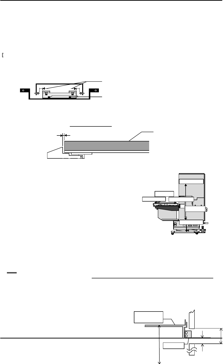
13-37] TY Cam Clamp Bracket Adjustment
Loosen the TY cam clamp bracket and adjust so that it can pass through the center of the eject
bracket adjusted in the previous section, [15-32]. After adjustment is finished move the tray up
and down to verify that there is no interference.
[13-38 ] Tray Holder Lock Adjustment
After the tray is set, adjust so that the gap between the lock mounted on the underside of the
plate and the tray holder is 0.3 mm +/- 0.1 mm.
[13-39 ] Max, Min_Limit_Position
1) Select [PROPER], [Max/Min], and [TY] or [TZ] and
when each axis reaches the negative side or positive
side mechanical stopper position, press [SET] to
automatically enter the Proper data.
2) The [Min_Limit] and [Max_Limit] direction of each axis
is depicted in the figure below.
[13-40 ] Original_Position_TZ
1) Move the TZ-axis via inching so that device number 101 is at the discharge position and then
eject the tray at device number 101. Then inch the TZ-axis to a position where the distance
from the QP2 machine base surface to the top of the device 101 tray holder is 157 mm +/- 0.5
mm.
Note: When the TZ-axis is operated via inching it will not move if the shuttle retract limit
sensor is not on. Also note that the tray cover and tray holder axis will come in contact if
the TZ-axis is inched prior to TZ-axis interlock sensor adjustment and if it is inched when
the shuttle has discharged the tray holder from the tray rack. Exercise due caution if the
axis must be moved during adjustment.
2) In this position select [PROPER], [DEVICE], [ORG.POS.TZ], and [SET] from the operation
monitor to automatically enter the Proper data.
[13-41 ] Guide Rail Adjustment
1) From the Original_Position_TZ position, adjust
the distance between the bottom surface of the
Stopper
157mm
±
0.5
mm
28mm
3.7
~
4.0mm
Tray holder
D101
Org.Pos.TZ
Min Limit
TY
-axis
Min Limit
TZ-axis
Max Limit
Max Limit
Loosen the bolts and adjust so that the gap is equally
distributed on the left and right.
Loosen these bolts to adjust.
0.3mm ± 0.1
Tray holder
FK-9F98-07 QP242E Training Text for Service Engineers
6th edition 13. MTU 71E Adjustment [15/24]
Fuji Machine Mfg. Co., Ltd. Okazaki
SMT Equipment Quality Assurance Dept.
Technical Support Div. Section No.2
13-15
stopper installed on the tray holder plate LM guide and the top of the bottom side guide rail
to between 3.7 and 4.0 mm.
2) Adjust the top side guide rail so that the gap between the bottom side and top side guide rails
is 28 mm.
[13-42]
TY-axis Interlock Sensor Adjustment
1) Move the TZ-axis up and down while viewing the servo counter display. Measure the number
of pulses for the width of the dog on the second level above the TY-axis interlock dog (set pitch
dog) that was installed at the Original_Position_TZ height when zero set was performed.
(I/O: IN X03F "O" when tripped)
2) Return the TZ-axis to the Original_Position_TZ position and adjust the sensor by moving it
up and down so that the center of the dog aligns with the center of the sensor. After
adjustment move the TZ-axis up and down again via inching, check that the width of the
dog is equally distributed on both sides from the center of the sensor, and record the servo
count value at that time in the Adjustment Inspection Work Manual.
3) Once adjustment is completed move the TZ-axis up and down to verify that it does not collide
with any other components and then tighten the bottom side dog mounting bolts only.
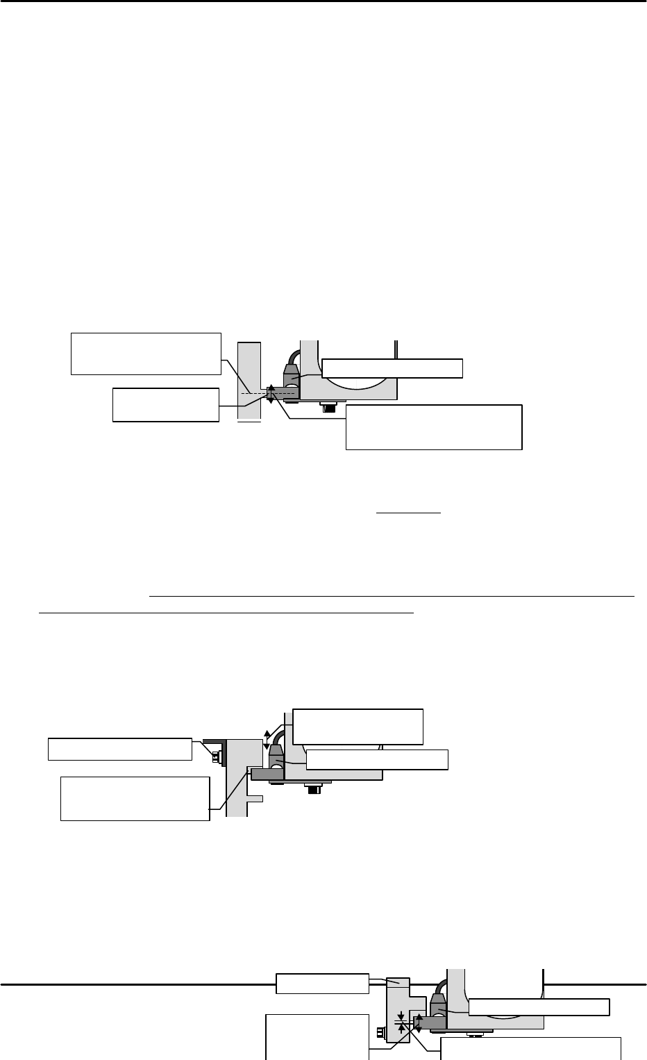
[13-43 ] TY-axis Interlock Dog Adjustment (Zero Count Position)
1) Display the servo count and move the TZ-axis to the + 50 pulse position via inching.
2) Adjust the dog attached to the inside of the top set pitch dog that was adjusted in the
previous section so that the sensor comes on in this position.
(I/O: IN X03F "O" when tripped)
3) When this dog trips the sensor on during zero setting this means that movement of the TY-
axis is possible. As a result this is premised on there being no interference between the
shuttle jaw and tray holder rollers when the sensor is on. Depending on deviations in each
machine, MTU, and shuttle, the appropriate position is not limited as a rule to the 50-pulse
position. In case of deviation align in accordance with the machine being adjusted so that
the TY-axis zero set operation is carried out from the zero count position with no interference.
4) Once adjustment is finished tighten the top interlock dog mounting bolts.
5) Move the TZ-axis up and down to verify that none of the dogs interfere with the sensors.
[13-44 ] TZ-axis Interlock (Shuttle Forward Limit) Sensor Adjustment 1
1) Move the TZ-axis to the Original_Position_TZ height.
2) Temporarily secure the outside dog to the inside dog and then provisionally secure both of
the dogs to the TY-axis interlock dog mounting bracket from the previous section.
3) Lower the TZ-axis to a position 1 mm below the Original_Position_TZ height and adjust the
sensor up and down so that the inside dog trips the sensor on.
(I/O: IN X01D "X" when tripped)
Adjust the sensor
up and down.
Find the number of pulses for
the width of the dog and align
the height at the center value.
TY-axis interlock sensor
Adjust so that the center
of the dog comes to the
center of the sensor.
TY-axis interlock sensor
Adjust so that the sensor
comes on in the TZ-axis
50-pulse position.
Move up and down to
adjust the inside dog.
Secure after adjustment
TY-axis interlock sensor
Comes on at a position 1 mm
(100 pulses) below
Org.Pos.TZ.
Inside dog
Adjust by moving
the sensor up
and down.
FK-9F98-07 QP242E Training Text for Service Engineers
6th edition 13. MTU 71E Adjustment [16/24]
Fuji Machine Mfg. Co., Ltd. Okazaki
SMT Equipment Quality Assurance Dept.
Technical Support Div. Section No.2
13-16
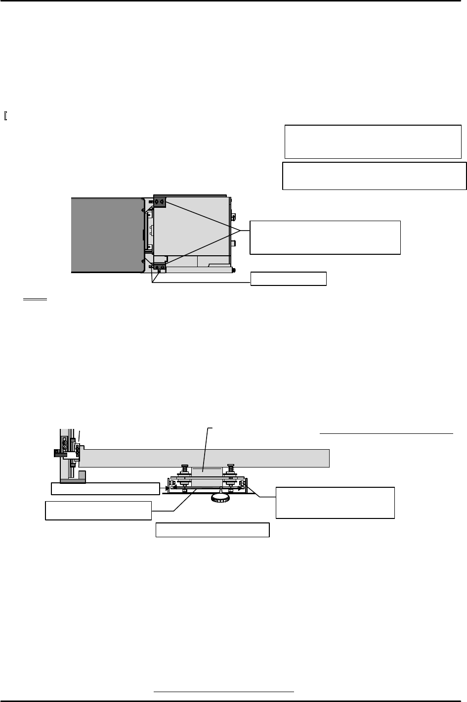
[
13-45] Securing the MTU71E in place
1) Attach the guide brackets on the left and right side
of the top of the MTU7 unit and secure the unit to the
machine side.
2) After securing the guide brackets in place, secure the
positioning blocks touching the sides of the brackets
as shown in the figure below.
Note: Carefully install the guide brackets so that the MTU71E cannot twist or turn.
[13-46 ] Shuttle Jaw Installation Position Adjustment and Left to Right Angle Adjustment
1) Adjust the shuttle jaw bracket installation position so that the two guide rollers on the end
of the tray holder plate are positioned equally in relation to the left and right end of the
shuttle jaw.
2) Use the dial gauge to measure the top of the stationary side claw in the X-direction and
adjust the shuttle jaw bracket angle such that difference between ends is within tolerance.
Once adjustment is completed verify that the guide roller positions remain equally
positioned.
[13-47 ] Original_Position_TY
1) Remove the blue duracon tray pusher from the shuttle.
2) There are two stoppers for adjusting the shuttle jaw opening amount that are installed in
the vicinity of the guide rollers of the stored tray holder plate. The stopper length should
be left about 10 mm from the mounting surface. The nut does not have to be tightened.
3) Move the TY-axis to a position where the guide rollers attached to the tray holder
mechanism are able to easily pass through the inside of the shuttle jaw (jaw opening is
about 10 mm). Check that nothing is causing interference and then slowly raise the TZ-axis
M8X30: cap screw
Lock washer, and W4 flat washer 8 each
M/C
MTU7
Secure the brackets with each side of
the bracket making contact such that
the unit cannot twist or turn.
Positioning block
M6X20: cap screw
Lock washer, and 4W flat washer 3 each
Shuttle bar
Shuttle jaw stationary side
( 0 ) ( )
Tolerance : within
±
0.2mm
Measure the top surface
in the X-direction
Shuttle jaw bracket
21
Check that both rollers are
equally positioned from the
end of the jaw.
Tolerance: Within +/- 0.2 mm