QP-242E 工程师培训手册 (6.0).pdf.pdf - 第96页
FK-9F98-07 QP242E Training Text for Service Engin eers 6th edition 11. Coplanarity Check Adjustment & Operation Check [ 2 / 4 ] Fuji Machine Mfg. Co., Ltd. Okazaki SMT Equipment Quality Assurance Dept. Technical Supp…

FK-9F98-07 QP242E Training Text for Service Engineers
6th edition 11. Coplanarity Check Adjustment & Operation Check [1/4]
Fuji Machine Mfg. Co., Ltd. Okazaki
SMT Equipment Quality Assurance Dept.
Technical Support Div. Section No.2
11-1
[CHAPTER 11] Coplanarity Check Adjustment & Operation Check
[11-1] Prior to Coplanarity Check (Bent Lead Detection) Adjustment
- A bent lead detection sensor is installed on top of the base of the placement module using a
laser transmission system.
- Equipped with an inspection function for detecting bent leads that is governed by JEDEC
standards.
- Applicable parts Parts with leads in four directions (QFP, VQFP)
Parts with leads in two directions (SOIC, VSOP, TSOP)
However, the ends of the leads of parts in the picked status must extend beyond the
diameter of the nozzle by more than 3 mm.
- Measurement accuracy : ± 0.01 mm
- Tolerance value input range : 20 ~ 3,000 um
- Measurement time : Approximately 3.5 seconds/ 4-directions
When bent leads are detected on a specified part, the
measurement time is added to the placement time.
【
11-2
】
Proper Data Measurement & Transmission
- Enter the values listed below in the appropriate data items and reboot the machine after the
Proper data is transmitted.
- The question mark “?” displayed in the Caption items represents the relevant module
number.
- Enter the appropriate value (front supply/rear supply) for Coplanarity X and Y.
- At present a negative value cannot be entered in F4G for the Coplanarity Z value.
(The value will display as a negative value on the machine.)
- The values for Coplanarity X, Y, and Z are temporary input values until automatic
measurement is carried out. These values will change at that time.
[Caption] [Value] [Record] <The following are in order
according to the module number.>
PLM? Coplanarity Check 1(Yes) 163, 178, 193, 208, 223, 238
PLM? Coplanarity LLL Qty 0(Not used) 761,1194,1627,2060,2493,2926
PLM? Coplanarity Calculation 0(Last) 762,1195,1628,2061,2494,2927
PLM? Coplanarity Recovery Time 1 763,1196,1629,2062,2495,2928
PLM? Coplanarity Z Correction 0(Not used) 764,1197,1630,2063,2496,2929
PLM? Coplanarity Recovery Offset 0 765,1198,1631,2064,2497,2930
PLM? Coplanarity LLL Y Depth 0(Not used) 766,1199,1632,2065,2498,2931
PLM? Coplanarity X -184000/184000 767,1200,1633,2066,2499,2932
PLM? Coplanarity Y -218000/218000 768,1201,1634,2067,2500,2933
PLM? Coplanarity Z 4294957400 769,1202,1635,2068,2501,2934
PLM? Coplanarity Y Speed 347(34.7%) 770,1203,1636,2069,2502,2935
PLM? Coplanarity Data Upload 0(No) 771,1204,1637,2070,2503,2936
PLM? LLL Port 3 896,1329,1762,2195,2628,3061
PLM? LLL Upload port 1 897,1330,1763,2196,2629,3062
[11-3] Jig Preparation
In addition to a dial gauge the following jigs are also needed for coplanarity check adjustment
work and automatic measurement.
1) Jig plate : BHPJ-0570 (28 mm square, t= 0.7 mm)
2) Measurement nozzle : Specialized nozzles are used that depend on the head type.
ABHPJ-6430 (single type)
ABHPJ-6440 (index type)
[11-4] Positioning Key Parallel Adjustment
Attach the dial gauge on the placement head and adjust the key that has been installed on the
top of the base so that it is parallel to the X-axis within 0.01 mm.
FK-9F98-07 QP242E Training Text for Service Engineers
6th edition 11. Coplanarity Check Adjustment & Operation Check [2/4]
Fuji Machine Mfg. Co., Ltd. Okazaki
SMT Equipment Quality Assurance Dept.
Technical Support Div. Section No.2
11-2
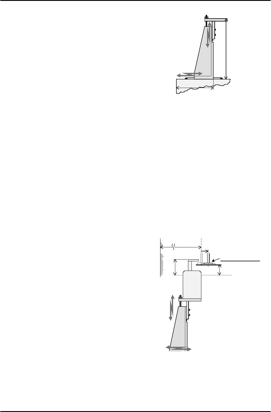
41mm
148mm
Module connection surface
M/C base
LLL sensor
installation surface
[11-5] Sensor Bracket Installation
1) Y-direction
Position using the key
2) X-direction
Align the side of the bracket so that it is 41 mm from
the side of the machine (module connection surface).
3) Z-direction
Align the sensor installation surface so that it is 148
mm from the machine base surface.
[11-6] Sensor Installation Surface Level Check
Attach the dial gauge on the placement head and check the levelness of the sensor installation
surface.
1) X-direction Levelness of the bracket must be within 0.05 mm.
2) Y-direction Levelness of the bracket must be within 0.05 mm.
(If the tolerance is exceeded the bracket needs to be replaced.)
[11-7] LLL Sensor Installation
Attach the dial gauge to the placement head and secure the sensor in position such that the
side of the sensor is parallel to the Y-axis within 0.05 mm.
[11-8] LLL Sensor Height Adjustment
Adjust the sensor height so that the top of the sensor head is 16,000 pulses (24 mm) above the
top surface of the board (Z0).
[11-9] LLL Sensor X-direction Positioning
1) Install the Proper data measurement nozzle
for coplanarity check on the nozzle holder; use
the I/O command to turn on the vacuum and
pickup the jig plate.
2) Use the dial gauge to align the jig plate
parallel to the Y-axis.
The parallelism to the Y-axis must be within
0.01 mm.
3) Move the placement head to a position where
there is nothing to cause interference around
the sensor and then raise the Z-axis height to a
position 11,167 pulses (16.75 mm) above the
top surface of the board (Z0).
4) Be particularly careful that nothing is
interfering with the sensor and then move the
X-axis position toward the inside by only 4,000
pulses (10 mm) from the Limit Position on the
side on which the coplanarity sensor is
installed.
5) Move the placement head in the Y-direction to
the position where the sensor head aligns with the center of the nozzle.
6) In this status then fine adjust sensor bracket installation in the X-direction so the sensor is
in a position where the red LED on the top of the sensor changes from being on (untripped)
to off (tripped).
7) Lastly, check again that all of the bolts have been tightened, that the alignment marks exist,
and that the wiring connectors are secured.
Return 10mm, 4000 pulse.
(67.5mm)
Top surface of
board (Z0)
24mm
Measurement pos.
LLL sensor
Limit Position X
16.75mm
Move the bracket
to the position
where the red LED
goes ON/OFF.
Fine adjust the
sensor head
height
Module connection surface

FK-9F98-07 QP242E Training Text for Service Engineers
6th edition 11. Coplanarity Check Adjustment & Operation Check [3/4]
Fuji Machine Mfg. Co., Ltd. Okazaki
SMT Equipment Quality Assurance Dept.
Technical Support Div. Section No.2
11-3
[11-10 ] Proper Data Measurement
1) Transmit the program created for measuring Proper data to the foreground of the machine.
The program can also be transmitted to the background but it must then be changed to the
foreground prior to the start of measurement. If a suitable program is not used the jig
cannot be positioned via vision processing.
(1) Part data
Enter the jig plate X and Y dimensions (X & Y = 28mm) as the Body size X and Y values.
Enter the jig plate thickness (h = 0.7 mm) as the Component height. Select the Lighting
and Vision type to match the camera type.
Lighting CCD=0, LS=3
Vision type CCD=10, LS=250
Enter Copla_PROP_I or S as the nozzle name.
(2) Nozzle data
Set so that nozzle check is not performed.
(3) Production program
Set the part data specified in (1) above for the first device used in the first sequence.
2) If work is continued from section 13.9 and the jig plate has already been picked, then install
the nozzle to be used if necessary and execute the following work.
Carry out the following command operation to turn on the vacuum and enable the START
ready status; [SET] (F5), [PROPER] (F3), input the ID code?, select the Mod No.?, [ETC] (F5),
[COPLA] (F3). Note that the [COPLA] (F3) command will only display if Coplanarity
Check is set to “1” (Yes).
Next, pickup the jig plate if necessary. The tip of the nozzle should be directly above the
cavity in the plate at this time. Furthermore, the plate should be picked in a status subject
to as little rotation deviation as possible.
3) Move the placement head to the position that satisfies the conditions given below in order to
set a position that is suitable for Proper data measurement. Directly input the provisional
Proper data value using [SET] (F1). Be careful that the sensor head does not make contact
with the jig during the course of this work.
(1) Y-direction Near the center of the sensor head (visual check)
(2) Z-direction Near the middle between the sensor head beam emitting mechanism
and the beam reflector (visual check)
(3) X-direction Within 400 pulses toward the rear from the red LED ON/OFF position
4) Press START to begin automatic measurement.
Repeat measurement twice in the order given below to complete measurement.
Vision process jig plate à Measure in X-direction à Measure in Y-direction
5) Once measurement is completed remove the jig plate from the nozzle holder and remove the
nozzle used for measurement and then cut the vacuum off using either the I/O command or
the part reject command to complete the work.