QP-242E 工程师培训手册 (6.0).pdf.pdf - 第21页
FK-9F98-07 QP242E Training Text for Service Engineers 6th edition 3. QP242E Initial Adjustment (2) [ 4 /12] Fuji Machine Mfg. Co., Ltd. Okazaki SMT Equipment Quality Assurance Dept. Technical Support Div. Section No.2 3-…

FK-9F98-07 QP242E Training Text for Service Engineers
6th edition 3. QP242E Initial Adjustment (2) [3/12]
Fuji Machine Mfg. Co., Ltd. Okazaki
SMT Equipment Quality Assurance Dept.
Technical Support Div. Section No.2
3-3
specified. (V1.40 or newer)
256: Enable Operation of the old type sliding remover. (V1.49 or newer)
512: Record the robust trace
2048: Nozzle drop prevention (soft take-off only when picking up tray parts. This setting should be used only for modules which
use single holders with a spring-back amount of 3.5mm.) (V1.80 or newer)
4096: For tray pick-up confirmation function
32768: For modules which use single holders with a spring-back amount of 3.5mm. (V1.80 or newer)
Note 4: Machine Status A
1: F-mark relief command
8: Remote command permission
32: Machine stops after bad mark reading if all placing sequences are skipped. When restarted, operation begins with mark
reading. (V1.80 or newer)
Note 5: Machine Status B
1: Module production continuation (this is different from the independent function. When an error stop occurs, production
continues only at modules which follow the error stop module. Operation is stopped at modules located before the error
stop module.)
2: Idling with vision processing (If this function has been used, be sure it is disabled before shipment.)
4: Nozzle bend measurement function (Usable only for round nozzles at CCD camera with back lighting.)
16: Displays the acquired image during automatic operation (V1.80 or newer)
256: For tray direction (V1.90 or newer)
512: Movement change for package type 5*, 6*(V1.90 or newer)
Note 6: PLM* Module Width
At F4G versions prior to V2.12, with a C/C version prior to V2.01, set as "MQ2*S7:PLM* spare" (spare under PLM*
Nickname). Proper data created at C/C versions prior to V2.01 should be transmitted back to the host first, and then
transmitted to the machine.
Note 7: PLM* Escape Position Z
Old Z-axis Zero Setting : Single Head Module which installed Camera type 7 = 2666 (Others =0)
New Z-axis Zero Setting : All of Module = 2000
* Set PLM2 to 6 in the same manner.
* When changing and then reusing previous Proper data, verify that the all the following values are set to
"0":
Center_Offset_X,Y
Final_Offset_X,Y,Q
Zero_Offset_Q
If an MTU is used, also verify that the "Zero_Offset_TY,TZ" item is set to "0".
2) Start up the machine by [RESET] + [POWER ON]. The following then displays in yellow: PLM Start
Processing, Memory Backup NG, Transmit Proper Value.
3) Transmit the temporary Proper data edited at step 1) above to the machine.
4) After the Proper data is transmitted, the yellow character display clears and "S/W Transmitting"
displays, indicating that the Proper data is automatically being transmitted to each module from the
ICM. When completed, "PCM Parameter" displays, indicating that the parameter data is
automatically being transmitted to each module from the ICM. When all transmissions are
completed, "Reset Start Executed, Turn Power Off" displays in yellow, indicating that the Proper data
transmission operation is completed.
* If the automatic parameter transmission fails, transmit the parameter data as described below.
[3-2] Parameter Transmission Procedure
1) While pressing the [F4] key, turn the power on. This will start up the machine in the mechanical
check mode.
2) In response to the [Max Module No.?] prompt, enter the number of modules being used at the
machine in question. [Number of modules] à [CR].
3) "PLM Start Processing, S/W Transmitting" then displays in yellow. Wait for approximately 5
minutes.
4) Use the following commands to transmit the parameter data to all the modules:
[PARAMETER] à [PRM TRAN ] à [ALL PLMS] à [YES]
* If the [Parameter] screen fails to display, reset the machine (power off), then begin again from step 1
above.
5) The transmission is complete when "Parameter For PLM" displays in yellow and the system returns
to the original screen.
* Thereafter, the mechanical check mode can be used for sensor adjustments, etc., as necessary.
FK-9F98-07 QP242E Training Text for Service Engineers
6th edition 3. QP242E Initial Adjustment (2) [4/12]
Fuji Machine Mfg. Co., Ltd. Okazaki
SMT Equipment Quality Assurance Dept.
Technical Support Div. Section No.2
3-4
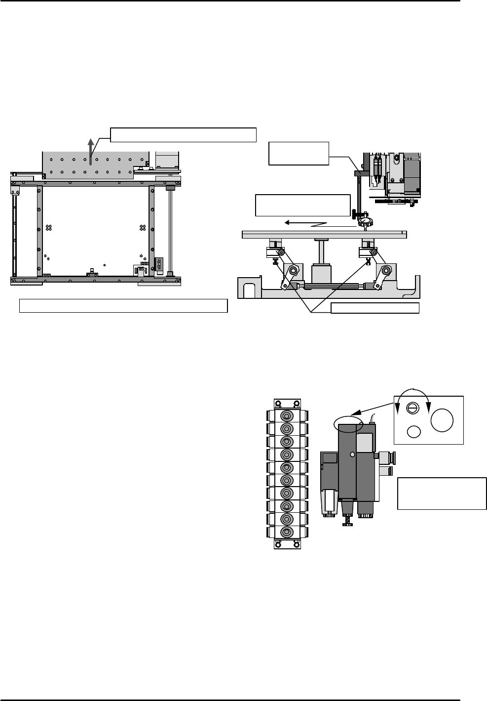
[3-3] Lifter Plate Height Measurement
1) Remove the backup plate from the rear of the machine (or from the front of the rear-loading
machines), and adjust the conveyor to its widest setting.
2) Using a jig, set a dial gauge on the X,Y robot. Use a calibrated techo type dial gauge.
3) Turn the "Y023 CNVYR BRD CLMP" I/O on to raise the table.
4) Measure the heights of the table's 4 corners and verify that the dial gauge reading is "0".
If the reading is other than "0", use the adjusting bolts to adjust the height.
5) After verifying the dial gauge reading, take measurements at 9 points on the table.
[3-4] Air Valve Throttle Adjustment
Open the machine's rear door and set the valves (located on the sides of the left and right supports) as
shown below.
Ø Lifter cylinder boa (old)
Valves at right-side support (from top) Number of turns (from full close)
1) Board stopper up 2 turns
2) Board stopper down 2 turns
3) Conveyor board clamp low-speed 0.5 turns
4) Conveyor board unclamp low-speed 0.75 turns
5) Conveyor board unclamp high-speed 0.75 turns
6) Conveyor board clamp high-speed 4.25 turns
7) Nozzle shutter close (for single nozzle) 2 turns
8) Nozzle shutter open (for single nozzle) 2 turns
9) Nozzle changer up (for single nozzle) 1.25 turns
10) Nozzle changer down (for single nozzle) 2 turns
Valves at left-side support
11) Board vacuum (vacuum break) 1 turn
12) Discharge time adjusting throttle
(6 turns from full open)
Ø Lifter Cylinder Boa (new)
Valves at right side support Numbers of turns(from fully closed position)
3) Conveyor board clamp low-speed 0.75 turns
4) Conveyor board unclamp low-speed 1 turn
5) Conveyor board unclamp high-speed 1.25 turns
6) Conveyor board clamp high-speed 5 turns
Settings for other valves are the same for lifter cylinder boa up (front) .
1 2 3
4 5 6
7 8 9
1
( )
2 ( )
3 ( )
4 ( )
5 ( )
6 ( )
7 ( 0mm )
8 ( )
9 ( )
Measure with table raised
Tolerance: Overall variation should be within 0.1mm
Remove the backup plate
Table
Measure table surface
using the dial gauge
Height adjusting bolts
Jig for setting
dial gauge
⑪
12)
1)
2)
3)
4)
5)
6)
7)
8)
9)
10)
Faster Slower
Discharge time
adjusting throttle
CW rotation: slower
CCW rotation: faster
FK-9F98-07 QP242E Training Text for Service Engineers
6th edition 3. QP242E Initial Adjustment (2) [5/12]
Fuji Machine Mfg. Co., Ltd. Okazaki
SMT Equipment Quality Assurance Dept.
Technical Support Div. Section No.2
3-5
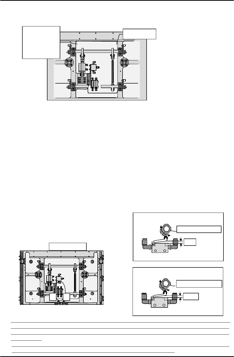
•How to distinguish lifter cylinder boa up front & rear.
Boa up (front) = Cylinder side and joint side arm width the same (10mm).
Boa up (rear) = Cylinder side is 18mm longer than the joint side.
[3-5 ] Table Mechanical Valve Adjustments
Note: The following adjustment should be performed only after the lifter plate height
measurement is completed.
1) High-speed cam adjustment for DOWN motion
1. Lower the lifter plate to a point 7mm below the UP limit.
2. Insert a 3mm spacer beneath the lever which presses the mechanical valve switch, then
press the lever against this spacer and secure the cam, making sure that the cam is
against the lever.
2) High-speed cam adjustment for UP motion
1. Position the lifter plate at its DOWN limit position.
2. Insert a 2.5mm spacer beneath the lever which presses the mechanical valve switch, then
press the lever against this spacer and secure the cam, making sure that the cam is
against the lever. (The lifter plate is probably at its DOWN limit at this time, leaving no
space to insert your hand in order to secure the cam. Therefore, make a mark to show
the cam and shaft positional relationship, then raise the lifter plate to its UP limit
position and secure the cam at the marked position. Because the PCB is subjected to
impacts each time this cam adjustment procedure is performed, be sure to perform it
correctly
the first time.)
Table mechanical valve adjustment
Turn the cam to adjust as shown below.
(Be sure to note the cam
direction)
* Note: Although the loading cycle time measurement procedure is described in section [9-1], the
air valve and mechanical valve adjustments performed as described in sections [4-4] and [4-5]
should be readjusted so that they are as close as possible to the reference cycle time values
shown below.
Reference cycle time values: Loading time (4.11 sec) = unclamping time (0.64 sec) + board
unloading and board loading time (2.26 sec) + clamping time (1.21 sec)
1 2
Machine rear
Table bottom
(1) High-speed cam for board DOWN limit
Adjust (turn) to 3mm
3mm
Lifter plate positioned at 7mm below the UP limit
(2) High-speed cam for board UP
Adjust (turn) to 2.5mm
2.5mm
Lifter plate positioned at
DOWN limit0
Width 10mm
•
Boa up
front
à width 10mm
•Boa up rear
à width 18mm