QP-242E 工程师培训手册 (6.0).pdf.pdf - 第70页
FK-9F98-07 QP242E Training Text for Service Engineers 6th edition 8. MTU6 Adjustment [ 2 /16] Fuji Machine Mfg. Co., Ltd. Okazaki SMT Equipment Quality Assurance Dept. Technical Support Div. Section No.2 8- 2 ALM OUT 5 0…
FK-9F98-07 QP242E Training Text for Service Engineers
6th edition 8. MTU6 Adjustment [1/16]
Fuji Machine Mfg. Co., Ltd. Okazaki
SMT Equipment Quality Assurance Dept.
Technical Support Div. Section No.2
8-1
[CHAPTER 8]
MTU6 Adjustment
Note: Cut the power to the machine before connecting the MTU. If the by-pass key is
inserted in the mechanical switch of the MFU specifications safety door, remove
the key and put it in the MTU cover. If the key is left inserted in the MFU
specifications switch this will disable the MTU front safety door by-pass key
which can lead to damage.
[8-1] Prior to Adjusting the MTU6
- Since layered stacking of trays is not possible on the MTU6, the number of part types that can be
loaded increases to between 50 and 100 types in comparison to the MTU7 (MTU7 can handle from
10 to 20 part types).
- On modules that use the MTU6 it is possible to switch from an MTU6 to MFU and vice versa.
When changing from an MTU6 to an MFU, safety fence replacement work is also included. Check
the specification manual and be aware that if this option is included a spare fence will also be
shipped. When an MTU6 is installed on an MFU module, in some instances Proper data
measurement will be necessary.
- When an MTU6 unit is connected to the machine, it must be connected with the machine in the
zero set complete status. Also verify that the shuttle jaw and tray holder do not interfere with each
other.
- When disengaging an MTU6 unit from the machine, separate the shuttle jaw and tray holder and
also verify that the shuttle is advanced forward before beginning work. The shuttle may be
damaged if it is at the retract limit. (Remove after carrying out the magazine replacement
command operation [POSITION], [MTU], [EXCHG MAG.], and press START.)
- MTU6 Specifications
Suitable machine : QP-242 600 type and 760 type
Number of part types that can be loaded : 50 types/50 levels (Large parts tray), 100
types/50 levels (Small parts tray)
Tray stacking : Not possible
Tray size : 335 x 250 mm (1part type/level)
160 x 250 mm (2 part types/level)
Minimum tray thickness : 4 mm
Maximum tray thickness : 7.8 mm (When stored in 10 mm pitch)
Maximum load weight per tray magazine : 400 g
Empty tray removal : Not possible
TY-axis : 0.0833 mm/Pulse (1 mm/12 Pulses)
TZ-axis : 0.01 mm/Pulse
Required number of magnets : New model 200, existing model 100 for total
of 300 magnets/MTU
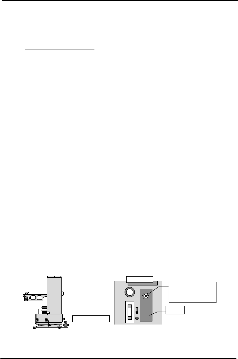
[8-2] Timer Adjustment
Remove the MTU6 lower control box cover and set the timer on the relay board
positioned on the left side to "0.4".
Control box cover
OMRON H3FA-A
L
S
Timer
Set the timer two scale
graduations from S.
This is equal to a time
of 0.4 seconds.
Relay board
FK-9F98-07 QP242E Training Text for Service Engineers
6th edition 8. MTU6 Adjustment [2/16]
Fuji Machine Mfg. Co., Ltd. Okazaki
SMT Equipment Quality Assurance Dept.
Technical Support Div. Section No.2
8-2
ALM
OUT
5
0.04 5
SENS
TIME (SEC)
MODE
red
blue
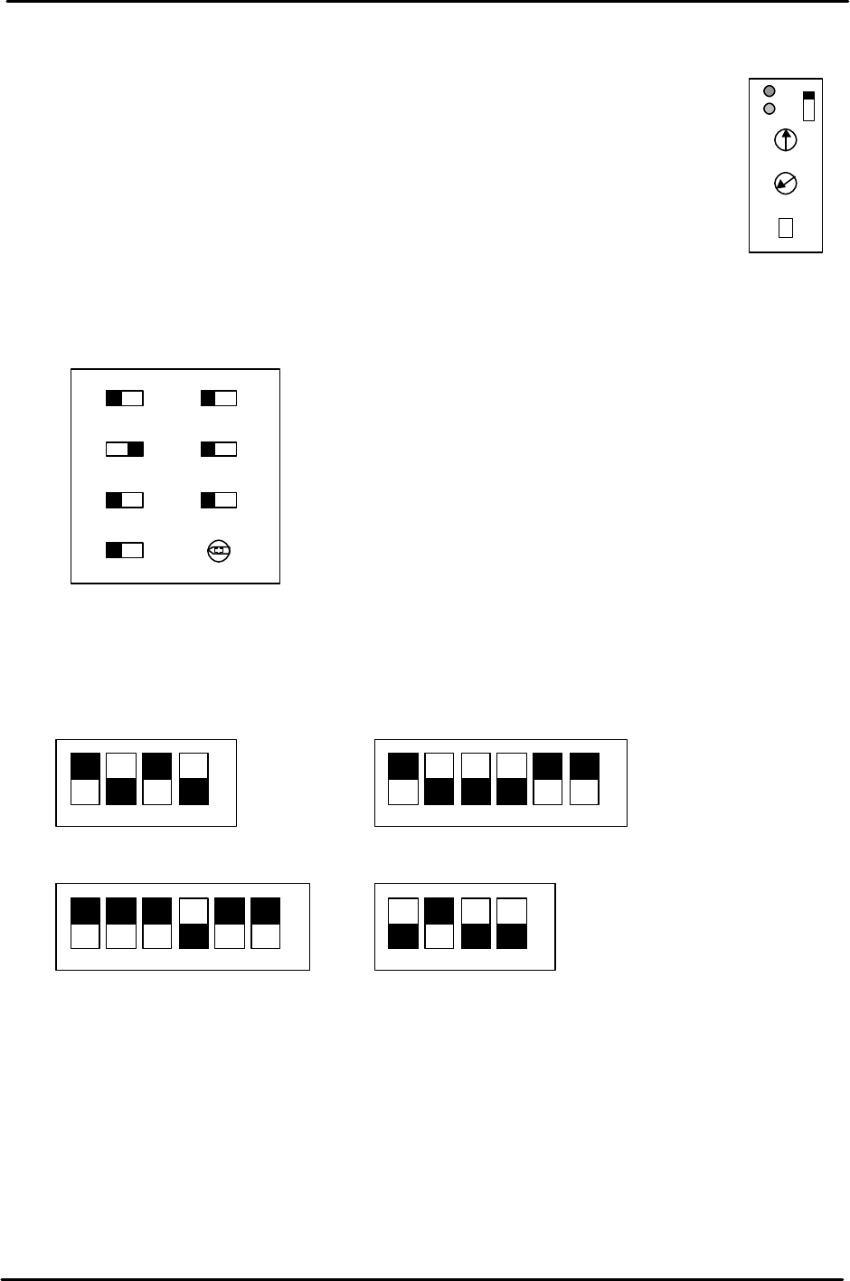
[8-3]
Tray Storage Check Sensor Amp and Controller Settings
1) Tray storage check sensor amp settings
- If there are two amps with a controller attached then set MODE to "5".
If there is one amp and no controller then set MODE to "1".
- For MODE 1 setting, turn the SENS volume until the red and blue lamps both go
out. Next turn the volume back until both lamps light up. Set the volume back
one scale graduation further from that level.
For MODE 5, first turn the volume until the red lamp lights up then turn the
volume back until the blue lamp lights up.
Turn the volume back one more scale graduation from that level and set there.
- Set the Time volume to Min. (0.04).
2) Tray storage check sensor controller settings
[8-4] Servo Amp Dip Switch Settings
Set each of the servo amp dip switches as shown below.
1 2 3 4 5 6 1 2 3 4
1 2 3 4 5 61 2 3 4
à NO
à NO
à NO
à NO
3SA1 SW
3SA2 (Amp left side)
No.1EV CONT SW2
No.1EV CONT SW1
Min Max
RANGE
SYNC
IN2IN1
MODE
TIME
TIMER
NORMNORM
OR
OFF 1S
0・S
П
FK-9F98-07 QP242E Training Text for Service Engineers
6th edition 8. MTU6 Adjustment [3/16]
Fuji Machine Mfg. Co., Ltd. Okazaki
SMT Equipment Quality Assurance Dept.
Technical Support Div. Section No.2
8-3
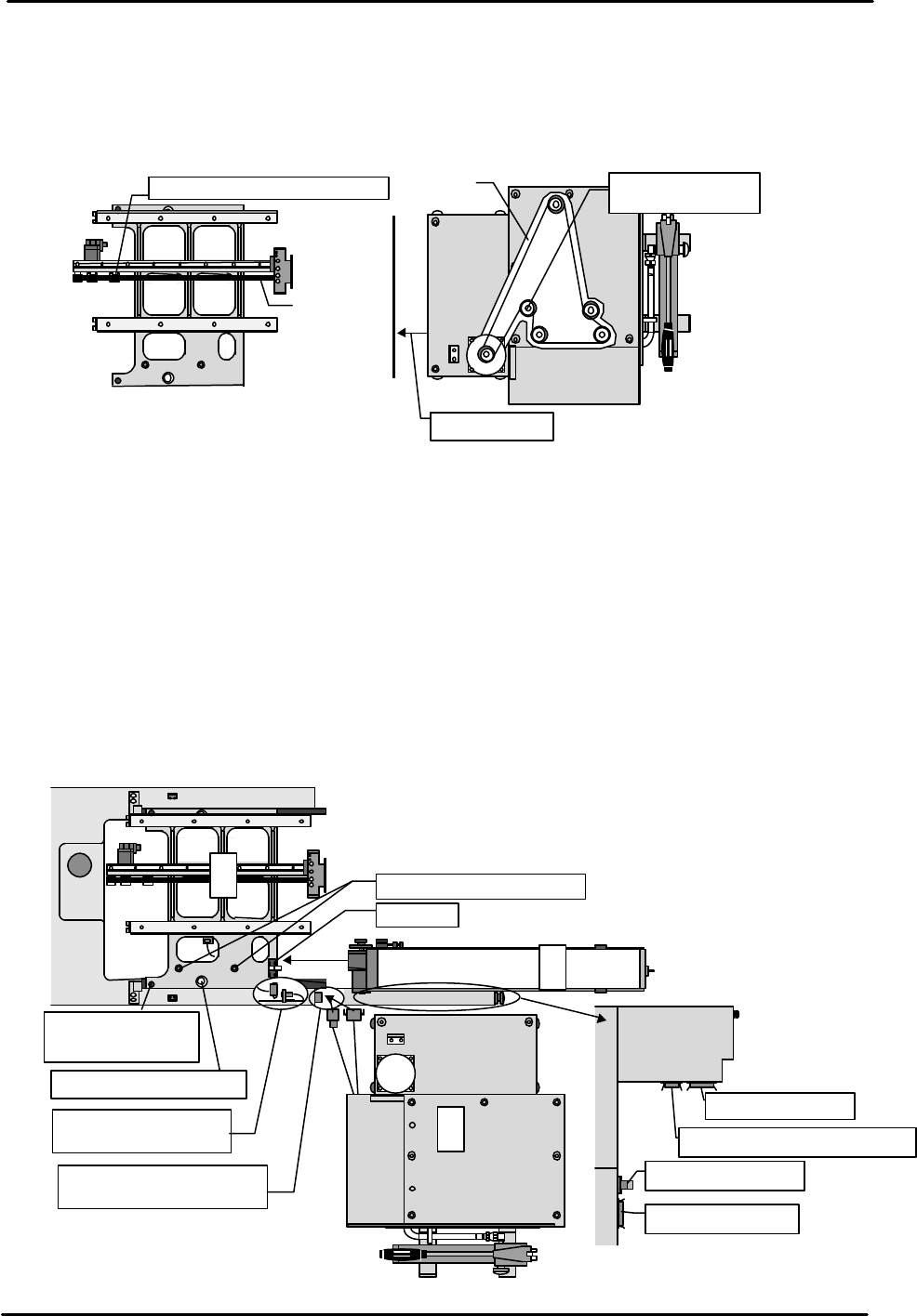
[8-5] TZ-axis and TY-axis Timing Belt Removal
1) Open the MTU safety door and loosen the belt tension adjustment pulley.
2) Remove the lower rear cover and then remove the TZ-axis belt.
3) Loosen the TY-axis belt tension adjustment pulley located on the shuttle and then
remove the belt.
[8-6]
MTU Provisional Connection
1) Shuttle assembly
Set the shuttle assembly using the MFU set jig positioning pin and then secure the
assembly to the machine using the knurled screw on the assembly side. After
securing in place connect the cable that protrudes from the shuttle assembly to the
machine.
2) MTU reject parts conveyor
Adjust before loading the reject parts conveyor on the MTU. (Refer to chapter 11) Set the MTU
reject parts conveyor with the conveyor inserted in the two conveyor positioning pins located
on the assembly side. After the conveyor is set, secure it in place using the torque clamp
located on the assembly side and connect the cable to the lower front fence.
3) MTU provisional connection
Since zero set adjustment cannot be performed if the MTU is connected to the
machine, use extension cords to temporarily connect the MTU power and signal
cables only. Provisionally position the MTU diagonal to the machine so that work
can be performed at the rear of the MTU.
View from top of
Belt tension adjustment pulley
Belt
Remove cover
Belt tension
adjustment pulley
View from
top of MTU
Belt
①
③
Clamp
Shuttle positioning pin
Connect the cable
from the shuttle
Connect the cable from
the MTU
MTU power cable
MTU I/O cable
MFU I/O cable
Reject parts conv. I/O cable
②
Reject parts conveyor
MTU
M/C
Camera
shuttle
Secure in place with
the left and right
knurled screws
Shuttle positioning pin
Front fence
M/C