QP-242E 工程师培训手册 (6.0).pdf.pdf - 第13页
FK-9F98-07 QP242E Training Text for Service Engineers 6th edition 1. QP242E Initial Adjustment (1) [ 4 / 6 ] Fuji Machine Mfg. Co., Ltd. Okazaki SMT Equipment Quality Assurance Dept. Technical Support Div. Section No.2 1…
FK-9F98-07 QP242E Training Text for Service Engineers
6th edition 1. QP242E Initial Adjustment (1) [3/
6
]
Fuji Machine Mfg. Co., Ltd. Okazaki
SMT Equipment Quality Assurance Dept.
Technical Support Div. Section No.2
1-
3
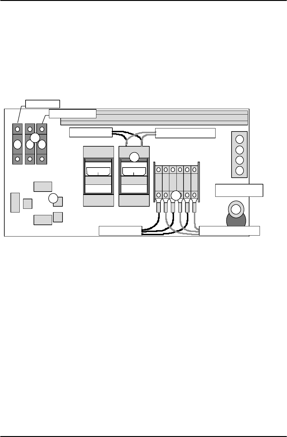
[1-2] Connecting the ICM and PLM
Perform the following procedure inside the top cover of the module at the Y-axis zero setting side:
1) Connect wires 901, 902, and 903. (As these are all power cables, be sure that they are secured
tightly.)
2) Connect CNP-10 and 12 as shown in the figure below. (Interlock wiring)
3) Connect wires 103 and 104. (As these are power cables, be sure that they are secured tightly.)
4) At odd-numbered modules, connect the cable from the ICM active hub to NET-1, and connect the
cable from NET-0 to the next module's NET-1. At even-numbered modules, connect the cable from the
previous module's NET-0 to NET-1, and leave NET-0 open.
5) Connect the air hose.
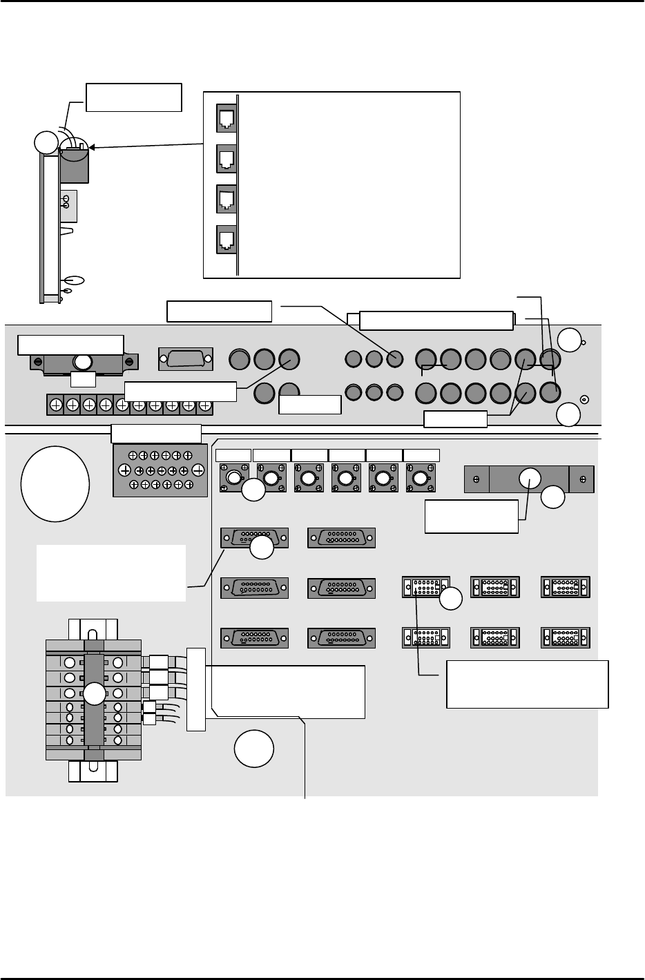
At inside ICM top cover:
1) Connect wires 901, 902, and 903.
(As these are power cables, be sure that they are secured tightly.)
2) Connect wires 103 and 104. (As these are power cables, be sure that they are secured tightly.)
3) Connect the interlock wiring to the MDL-I/F. (This cable is connected to GNP-12 at module 1.)
4) Connect each module's parts camera cable to the mutiplexer.
5) Connect each module's mark camera cable to the mutiplexer.
6) Connect each module's line scan camera cable and encoder cable to the CAM1-I/F and ENCODER1.
7) Connect the line scan camera's AV cable to CAM1-AV.
8) Connect the Arc net cable to the active hub.
9) Connect the air hose to the air coupler at the rear of the ICM.
901
901
902
902
903
903
ON
MITSUBI
SHI
C P 3 0 - B A
ON
MITSUBI
SHI
C P 3 0 - B A
CJ2
CJ1
CJ3
CJ4
NET 0
NET 1
104103
To next module From previous module
From previous module
To next module
CNP-10
CNP-12
To next module From previous module
Air hose port
1
2
3
5
4
C P 3 0 - B A
FK-9F98-07 QP242E Training Text for Service Engineers
6th edition 1. QP242E Initial Adjustment (1) [4/
6
]
Fuji Machine Mfg. Co., Ltd. Okazaki
SMT Equipment Quality Assurance Dept.
Technical Support Div. Section No.2
1-
4
At rear parts-supply machines, connect the [CRT-1B] cable to the rear of the operation monitor. Connect
the [BCD1CN1-FB] cable to [M1PCB1B] at the right side of the vision processing monitor. Connect the
[OPCN1] cable to [OPCN1].
Part name: Active hub
2
1
4
3
6
5
8
7
10
9
12
11
CAMERA IN
MONITOR IN
2
4
1
5
3
1
MONITOR OUT
2
1
4
3
5
CAMERA OUT
RS232C
CONTR
OL
ENCODER1 ENCODER3
CAM1-I/F
CAM3-I/F
CAM5-I/F
CAM2-I/F
CAM4-I/F
CAM6-I/F
MDL-I/F
1
2
3
From module 1 mark camera
From COGNEX board
Module
2
From module 1 parts camera
3
4
5
6
6
7
8
Arc-net cable
down
1
2
3
4
Viewed from front of active hub
Active hub wiring
1. To MP board
2. To Net-1 at module 1
3. To Net-1 at module 3
4. To Net-1 at module 5
ENCODER2
ENCODER4
ENCODER5
ENCODER6
1
4
5
6
7
To module 1
1
2
3
4
5
6
7
To Module 1
(GNP-12)
From line scan encoder (Used in
sequence from CN1, beginning
from smallest module number)
To COGNEX board
CAM1-AV
CAM2
-
AV
CAM3-AV CAM4-AV CAM5-AV CAM6-AV
901
902
903
103
104
Ground terminal block
I/O
View from
machine top
Part name: Multiplexer
To monitor
From line scan parts camera AV
(Used in sequence from CN1,
beginning from smallest module
number)
FK-9F98-07 QP242E Training Text for Service Engineers
6th edition 1. QP242E Initial Adjustment (1) [5/
6
]
Fuji Machine Mfg. Co., Ltd. Okazaki
SMT Equipment Quality Assurance Dept.
Technical Support Div. Section No.2
1-
5
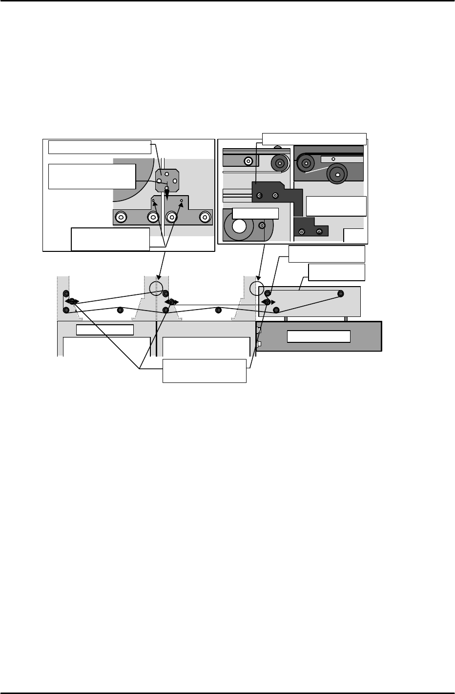
[1-3] Checking the Conveyor Parallelism and Linkage Chain Tension
1) Adjust the conveyor width to the width of a Fuji PCB.
2) Verify that the difference in width from the conveyor's entrance to exit (at each module) is within
0.5mm. Record the measured values on the record sheet.
3) Verify that a linkage bracket is present (for conveyor linkage) at the secondary conveyor rails of each
module.
4) Verify that the linkage chain tension is as prescribed.
Note: If the chain is too tight, the handle will not turn easily.
[1-4] Connecting power cable and an air hose, and transmitting F4G.
*
After ensureing 200V is on in the transformer, connect power cable to power box.
*
*
*
Chain
Sprocket
Conveyor linkage bracket
Insert bracket
between these pins
Slide to back of
bracket
IN conveyor
Last module
Chain tension
adjusting sprockets
IN conveyor
Module 1 secondary
conveyor rail
Conveyor linkage bracket