QP-242E 工程师培训手册 (6.0).pdf.pdf - 第47页
FK-9F98-07 QP242E Schooling Text for Service Engineer 6th edition 6. Proper Data Measurement [ 6 /20] Fuji Machine Mfg. Co., Ltd. Okazaki SMT Equipment Quality Assurance Dept. Technical Support Div. Section No.2 6- 6 [6 …
FK-9F98-07 QP242E Schooling Text for Service Engineer
6th edition 6. Proper Data Measurement [5/20]
Fuji Machine Mfg. Co., Ltd. Okazaki
SMT Equipment Quality Assurance Dept.
Technical Support Div. Section No.2
6-5
[6-7] Mark Read Pos. X,Y
1) Execute the following command sequence to turn on the camera lamp: [CAMERA] à
[CAMERA POS] à [MARK CAMERA].
2) While watching the image monitor, move the head so that the plate jig’s reference pin hole is
at the camera center.
3) With the reference pin hole centered, press the [SET] button to begin the automatic [Mark
Read Pos. X,Y] measurement. Leave the plate jig as it is when proceeding to the next
measurement item.
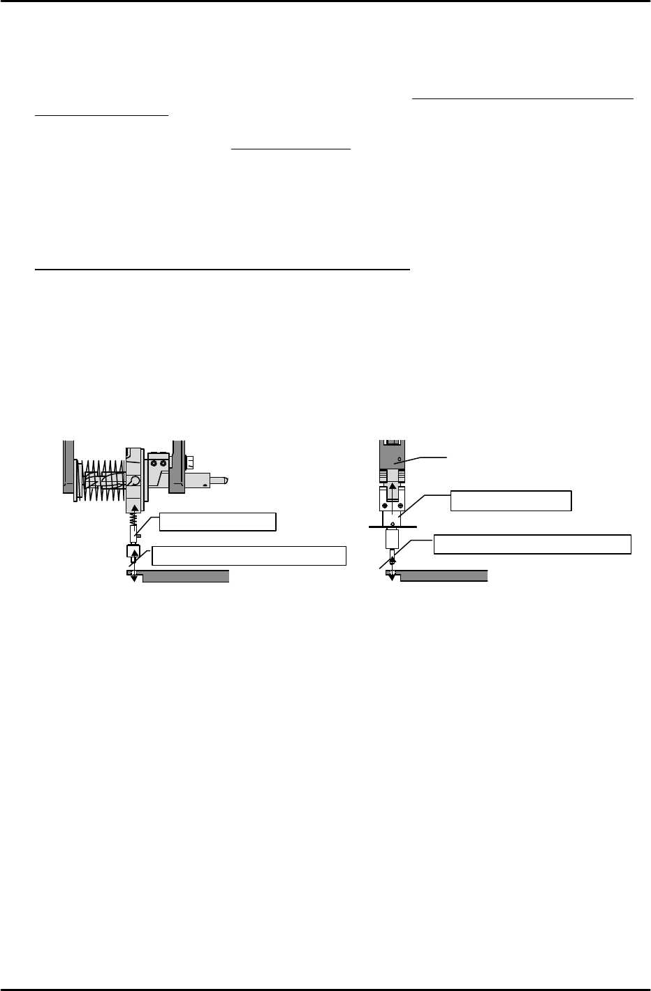
[6-8] Program_Origin_X0,Y0
1) Mount an X0, Y0 Proper data measurement jig in the holder.
2) With the plate jig still clamped as described at [7-7] above, move the head to find the position
where the measurement jig (mounted in holder) can be inserted smoothly into the reference
pin hole.
3) This is the Program_Origin_X0,Y0 position. Execute the following command sequence to
automatically enter this data:
[ETC] à [REF. POS.] à [X0/Y0] à [SET].
Jig for index type
Position where insertion is smooth
Plate jig
Jig for single type
Position where insertion is smooth
Nozzle shaft
Plate jig

FK-9F98-07 QP242E Schooling Text for Service Engineer
6th edition 6. Proper Data Measurement [6/20]
Fuji Machine Mfg. Co., Ltd. Okazaki
SMT Equipment Quality Assurance Dept.
Technical Support Div. Section No.2
6-6
[6-9] Placement_Height_Z0
* If measuring with a dial gauge, be sure that the gauge is calibrated.
1) Mount a 10mm adjustment nozzle at the index holder or the nozzle shaft.
2) Lower the Z-axis until the top face of the clamped jig makes contact with the nozzle bottom,
then set a dial gauge on top of the nozzle disk.
3) Slowly raise the Z-axis to the point where the dial gauge needle begins to move.
4) This is the Z0 position. Execute the following command sequence to automatically enter the
Placement_Height_Z0 value: [REF. POS.] à [Z0] à [SET].
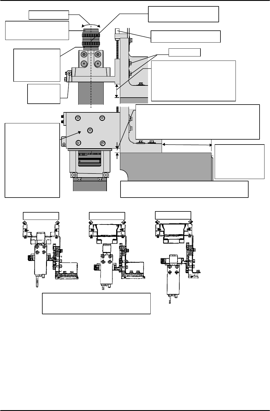
[6-10] Adjusting the Parts Camera Height, the Lens Aperture, and
the Temporary Focus
* There are six parts camera types (types 1, 2, 3, 4, 6, 7). Be sure that the correct camera type
is mounted (check specifications) before performing these adjustments.
1) Set the camera lens aperture and temporary focus as suitable for the camera type in question.
Note: The thickness of the collar between the camera and lens varies according to the camera type.
2) Adjust so that the distance from the side of the base to the end of the camera bracket is 42mm
(this applies for all camera types). (Details regarding 1-camera and 2-camera systems are
given later.)
3) Turn the adjusting bolt until the distance from the machine base to the camera bracket is
suitable for the camera type in question.
Plate jig
Dial gauge
10mm nozzle
Point where nozzle and jig make contact
For line scan cameras:
(Camera types 4, 7)
Aperture…2.8
Temporary focus…0.27
Align top face of lens
with the top face of the
blue lens bracket. This
position should be
approximately 0.27.
LOCK UNLOCK
2,8
4 A
22 22
0.25
0.3
4
8C16
2 1,4
0.4
JAPAN
For CCD cameras:
Aperture:
Camera type 1…2
Camera type 2…5
Camera type 3…4
b)Temporary focus:
Camera type 1…A little before 5
Camera type 2…Midway between 1 and 0.5
Camera type 3…Midway between 1 and 0.5
FK-9F98-07 QP242E Training Text for Service Engineers
6th edition 6. Proper Data Measurement [7/20]
Fuji Machine Mfg. Co., Ltd. Okazaki
SMT Equipment Quality Assurance Dept.
Technical Support Div. Section No.2
6-7
Camera type 3
Camera type 1 Camera type 2
Be sure that the bracket where the CCD
camera is mounted is correctly oriented.
M/C Base
Camera
BKT
Lock bolt
Height adjusting set screw
Camera type 1: 34.5mm
Camera type 2: 21.0mm
Camera type 3: 16.5mm
* These dimensions were
obtained during testing, and
are for reference purposes
Set screw for
camera Q
adjustment
Camera
collar
thickness
Camera 1: 11mm
Camera 2:2.0mm
Camera3: 1.4mm
Lens filter
Camera 1 25mm 1:1.4
Camera 2,3 16mm 1:1.4
Beware for tilt
Aperture and focus lock
screws face this direction
2,8
Camera BKT
M/C Base
Camera
42mm
Camera type 4,7: 25.0mm
(Lens
no.R4013H)
Camera type 4,7: 21.0mm (Lens no.R4034A)
However R4034A
front supply, index camera 7: 15mm
*Reference Value Only
Note: This is the
base end face,
not the module
base contact
surface.
22.0mm for index nozzle & front supply & camera
type 7. *Reference value only.
This bracket
changes when
index nozzle &
front supply &
Camera type 7 is
used. 15mm
lower in conditions
with camera
height different
than above.