QP-242E 工程师培训手册 (6.0).pdf.pdf - 第67页
FK-9F98-07 QP242E Training Text for Service Engineers 6th edition 7. Static Accuracy Measurement [ 5 / 6 ] Fuji Machine Mfg. Co., Ltd. Okazaki SMT Equipment Quality Assurance Dept. echnical Support Div. Section No.2 7- 5…
FK-9F98-07 QP242E Training Text for Service Engineers
6th edition 7. Static Accuracy Measurement [4/6]
Fuji Machine Mfg. Co., Ltd. Okazaki
SMT Equipment Quality Assurance Dept.
echnical Support Div. Section No.2
7-4
<<How to obtain the input value>>
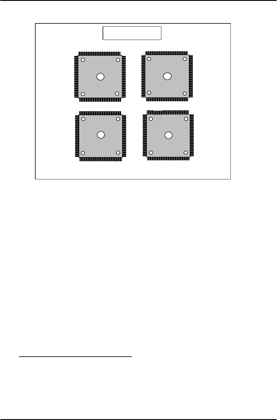
A total of four glass parts are placed as shown in the figure.
* The glass board and parts form a vernier scale (1 graduation is 0.00 25 mm) and it
is possible to measure how many graduations the conforming location (position where
the 4 leaded sides of a part match the pattern) deviates from the pattern center.
Center_Offset X and Y are obtained by (0? value - 180? value) / 2.
Final_Offset X and Y are obtained from the average value of all placed parts.
The sign of the input values for Center_Offset X and Y as well as Final_Offset X and
Y are obtained from the previous table.
i) After the values are input, place the parts again in automatic operation (step 5), and carry
out measurement to obtain a level of accuracy within the allowable tolerances.
3) Camera type 6I and 6S
a) Install the respective back light nozzles on the relevant module.
b) Set each glass board (prepared with double-sided tape) on the ICM conveyor.
c) Transmit each placement program to the machine.
d) In the case of an MFU set the glass part receiving jig in the specified slot. For an MTU set
the glass parts tray in the specified slot (tray holder). Then enter automatic operation and
place the glass parts.
e) Use the magnifying glass with attached monitor to measure the accuracy and then check the
placement accuracy.
f) Camera type 6I and 6S placement accuracy (Flip chip Module)
Verification of the placement accuracy is complete if the results fall with in the following
specification.
Placement Accuracy (3 sigma): ± 0.03mm
Once the accuracy check is completed transmit the Proper data to F4G and then save the
data.
180degrees
90degrees
Glass board
270degrees
0degrees
FK-9F98-07 QP242E Training Text for Service Engineers
6th edition 7. Static Accuracy Measurement [5/6]
Fuji Machine Mfg. Co., Ltd. Okazaki
SMT Equipment Quality Assurance Dept.
echnical Support Div. Section No.2
7-5
g) If the placement accuracy results exceed the allowable tolerance ranges then carry out
calibration (Center_Offset, Final_Offset).
h) Add the Center_Offset X and Y and Final_Offset X and Y values to the original value and
then directly enter the values at the machine using the following command operation.
[PROPER], [CAMERA], [ETC], [ETC], select [Center_Offset] or [Final_Offset] for input, use
the arrow keys to select X or Y, input the value and then hit return.
<<How to obtain the input values>>
A total of eight 60-pin glass parts are placed as shown in the figure above.
The glass board and parts form a vernier scale (1 graduation is 0.005 mm).
Measure how many graduations the conforming location (location where the 4 leaded
sides of a part match the pattern) deviates from the pattern center.
Center_Offset X and Y are obtained by (0 degree’s value – 180degrees’ value) / 2.
Final_Offset X and Y are obtained from the average value of all placed parts.
The sign of the input values for Center_Offset X and Y as well as Final_Offset X and
Y are obtained from the previous input value sign table.
i) After the values are input, place the parts again in automatic operation (step 5), and carry
out measurement to obtain accuracy within the allowable tolerances.
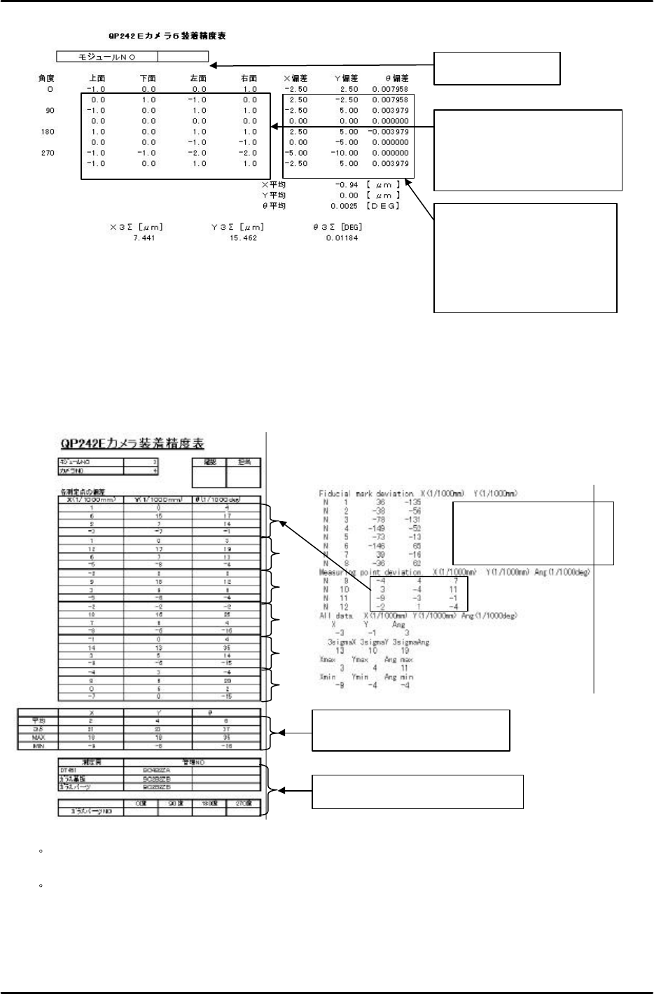
j ) If the placement accuracy falls within the allowable tolerance ranges then input the data
into a QP242E Camera 6 Placement Accuracy Table (Excel file: QP242E camera6placement
accuracytable.xls) and obtain a printout of the table.
Glass board for 60-pin parts
270degrees
270degrees
180degrees
180degrees 90degrees
90degrees
0degrees
0degrees
FK-9F98-07 QP242E Training Text for Service Engineers
6th edition 7. Static Accuracy Measurement [6/6]
Fuji Machine Mfg. Co., Ltd. Okazaki
SMT Equipment Quality Assurance Dept.
echnical Support Div. Section No.2
7-6
4) Results Tabulation
Once the placement accuracy of each camera type falls within the allowable tolerance
ranges, use the DT to carry out placement accuracy measurement six times (total of 24
points) in succession without changing the Proper data.
From the results enter the Measuring point deviation {X, Y, Ang (Q)} data in the
placement accuracy table (Excel file: Cameraaccuracystatisticstable.xls).
・ For camera type 1 since 32 points can be measured at one time, measurement does not
have to be repeated six times. One measurement (total of 32 points) completes the process.
・
For camera type 6 since eight points can be measured at one time, measurement is
completed after three rounds of measurement. For camera type 6 two glass parts are used
for each angle of the part.
1)
3)
4)
5)
6)
Does not have to be input since the
values are entered automatically.
Be sure to record the control number.
Results of measurement
using the DT for camera type
2, 3, 4, and 7
Input the deviation (number of
graduations). All other items are
calculated automatically and thus
do not need to be input.
Input the module No.
Enter this value in the placement
accuracy table created in the next
step 4).
Note: The Q value must be
converted into 1/1000 deg.